Cooling apparatus using boiling and condensing refrigerant

a technology of refrigerant and cooling apparatus, which is applied in the direction of lighting and heating apparatus, indirect heat exchangers, and semiconductor/solid-state device details. it can solve the problems of reducing heat conduction efficiency, affecting the projection of heat-receiving surfaces or refrigerant tanks, and affecting the heat-receiving

Inactive Publication Date: 2001-11-27
DENSO CORP
View PDF2 Cites 18 Cited by
  • Summary
  • Abstract
  • Description
  • Claims
  • Application Information

AI Technical Summary

Benefits of technology

The refrigerant tank is composed of a case and a cover plate that closes the front surface of the refrigerant tank. The cover plate may be made so that it extends beyond the upper and lower edges of the refrigerant tank, and holes for mounting a substrate carrying the hot objects may be formed through the extended portions of the cover plate. In this manner, the inner space of the refrigerant tank can be utilized more effectively, and resiliency of the extended portions help the hot objects to closely contact the heat-receiving surface. A resilient member such as a spring may be additionally used to further enhance the mounting resiliency. The duct for conducting cooling air may be formed integrally with the cover plate to simplify the whole structure of the cooling apparatus. The integrally formed duct also helps the cooling air to flow smoothly through the duct.
According to the present invention, the hot objects are easily attached to one surface of the refrigerant tank without being obstructed by other structures of the cooling apparatus. The radiator is connected to the refrigerant tank with a precise dimensional relation because the insertion length of the radiator is properly controlled. Moreover, the inner space of the refrigerant tank effectively utilized, and the hot objects are easily attached to the heat-receiving surface, even if the size of the hot objects are small and other components are mounted on the same substrate together with the hot objects.

Problems solved by technology

However, if the hot objects are computer chips that are mounted on a printed board, other components mounted on the same printed board interfere with projected portions on the heat-receiving surface or on the refrigerant tank.
On the other hand, if the insertion length is too small, the fin positioned closest to the refrigerant tank does not properly contact the refrigerant tank, thereby causing heat conduction efficiency to decrease.

Method used


Image

  • Cooling apparatus using boiling and condensing refrigerant
  • Cooling apparatus using boiling and condensing refrigerant
  • Cooling apparatus using boiling and condensing refrigerant

Examples


example 3

for the restricting insertion length is shown in FIG. 12. In this example, a spacer 22 is interposed between a shoulder 23 formed on the inner header plate 16c and the cover plate 7. The outer header plate 16d is connected to the inner header plate 16c at a right position via the position-setting portion 16e. The insertion length is restricted by the spacer 22, and therefore the radiator 5 is correctly assembled to the tank 4. Alternatively, the spacer 22 may be placed between the shoulder 23 and the bottom surface of the tank 4, as shown in FIG. 13. Though the spacer 22 is placed to support the inner header plate 16c both in the structures shown in FIGS. 12 and 13, the spacer 22 may be placed to support the outer header plate 16d. Further, plural spacers 22 may be used to support both the inner and outer header plates 16c, 16d, a s shown in FIG. 14. In the structure of FIG. 14, no position-setting portion 16e is required. The insertion length of the header tubes is properly restric...

example 5

is shown in FIG. 16. In this example, a recess 24 for receiving the header tank 16 is formed on the cover plate 7, so that the insertion length of the header tank 16 is restricted by the recess 24. In this structure, mechanical strength of the cooling apparatus 1 is enhanced because the bottom end of the header tank 16 can be soldered to the recess 24.

example 6

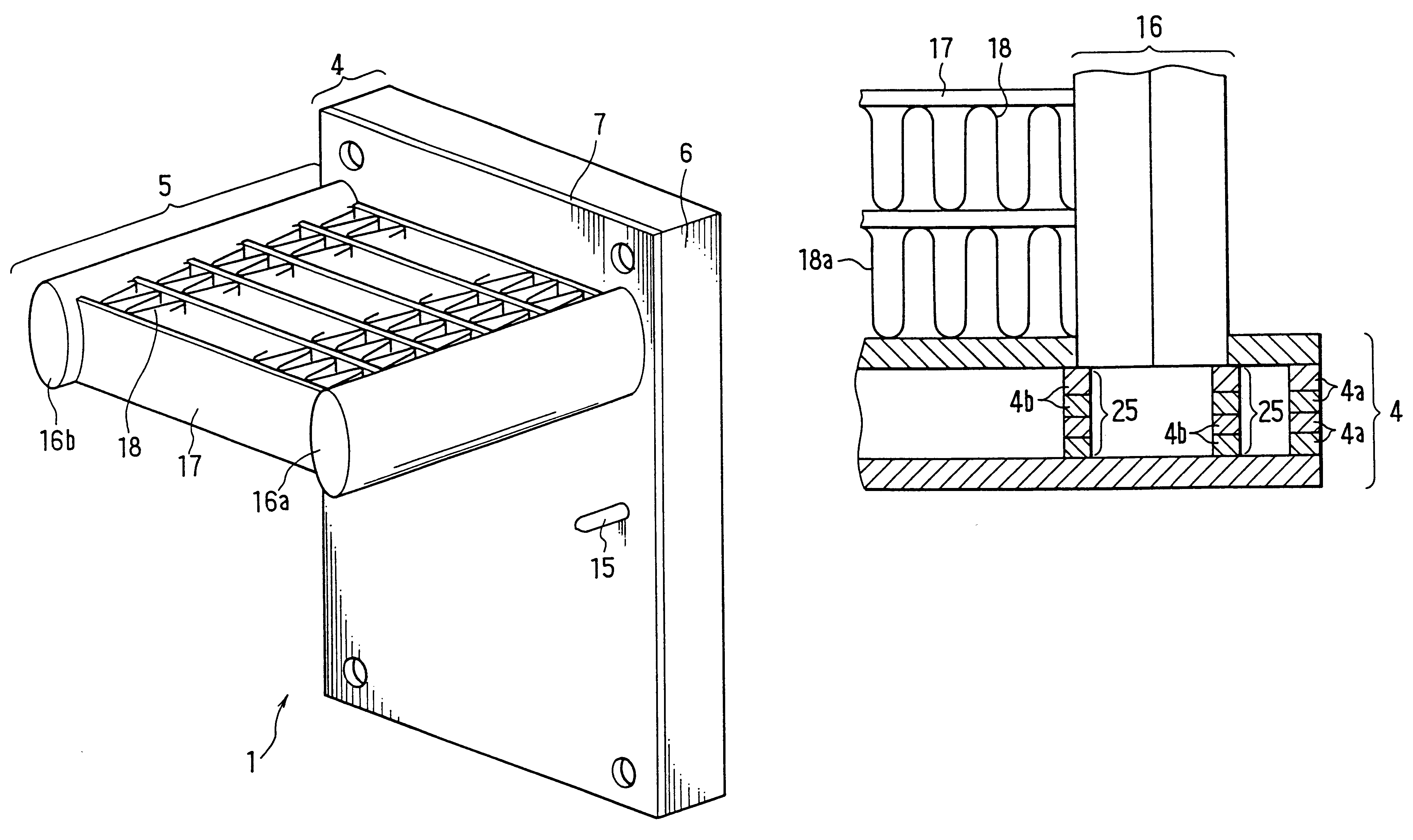
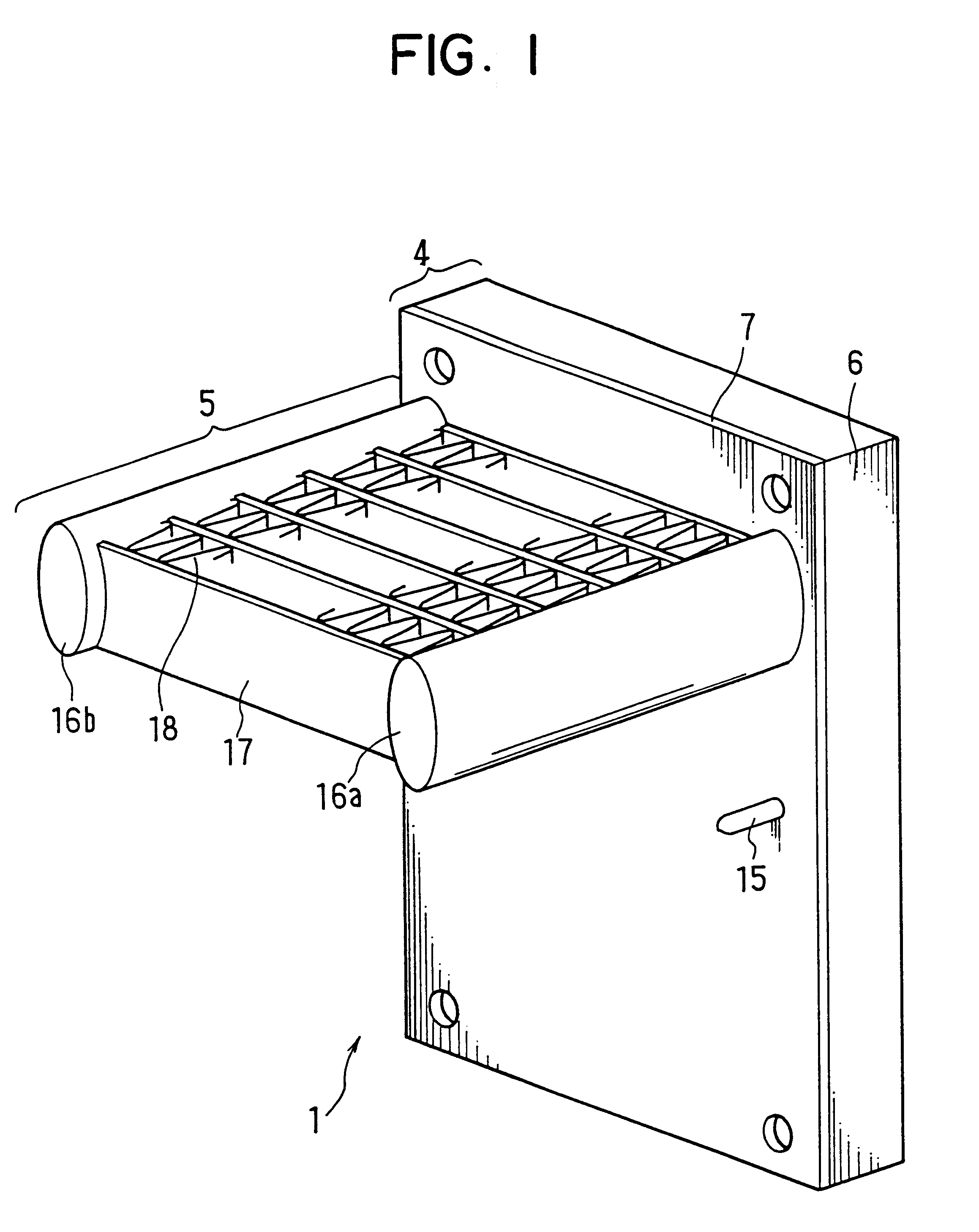
is shown in FIG. 17, in which spacers 25 are formed integrally with the refrigerant case 6. The spacers 25 support the header tank 16 to restrict its insertion length into the tank 4. The spacers 25 of FIG. 17 may be modified into a form shown in FIG. 18. When the refrigerant tank 4 is formed by laminating several plates 4a, a part 4b of the spacers 25 can be easily formed on the respective plates 4a. By laminating the parts 4b of the several plates 4a, the spacers 25 can be formed. The bottom end of the header tank 16 may be soldered to the upper surface of the spacers 25 to enhance the mechanical strength. In this case, a certain amount of solder is placed between the bottom end of the header tank 16 and the upper surface of the spacers 25, and the height of the spacers 25 is designed so that the insertion length becomes proper when the solder melts and the header tank 16 directly contacts the spacers 25.


PUM


Abstract

A cooling apparatus includes a refrigerant tank containing boiling and condensing refrigerant and a radiator for cooling the refrigerant. The radiator is connected to the refrigerant tank on a front surface thereof, and hot objects to be cooled are attached to a heat-receiving surface formed on a rear surface of the refrigerant tank. The refrigerant is circulated in the apparatus so that the refrigerant is vaporized in the refrigerant tank and condensed in the radiator. The radiator is connected to the refrigerant tank by inserting a pair of header tanks thereof into the refrigerant tank. The insertion length is controlled to obtain good heat conductivity between the radiator and the refrigerant tank and to avoid deformation of a radiator fin contacting the refrigerant tank. Holes for mounting a substrate carrying the hot objects may be made on enlarged portions of a cover plate closing the refrigerant tank. The heat-receiving surface may be elevated from the rear surface of the refrigerant tank to avoid interference between other components mounted on the substrate and the rear surface of the refrigerant tank.

Description

This application is based upon and claims benefit of priority of Japanese Patent Applications No. Hei-10-357381 filed on Dec. 16, 1998, No. Hei-10-357594 filed on Dec. 16, 1998, No. Hei-10-359958 filed on Dec. 18, 1998, and No. Hei-11-268740 filed on Sep. 22, 1999, the contents of which are incorporated herein by reference.1. Field of the InventionThe present invention relates to a cooling apparatus for cooling hot objects attached thereto by vaporizing condensed liquid refrigerant.2. Description of Related ArtA power unit cooler using boiling and condensing refrigerant has been known and used in an industrial field. Hot objects such as IGBTs attached to a heat-receiving surface of a tank containing refrigerant are cooled by evaporation latent heat of the refrigerant. The evaporated refrigerant is cooled down and condensed into liquid by radiating heat therefrom to cooling fluid such as cooling air. Since the hot objects such as IGBTs are packaged as a single unit, they can be easil...

Claims


Application Information

Patent Timeline
Patent Type & Authority Patents(United States)
IPC IPC(8): F25B23/00F28D15/02H01L23/34H01L23/427
CPCF25B23/006F28D15/0266H01L23/427H01L2924/0002H01L2924/00
Inventor TANAKA, HIROSHITERAO, TADAYOSHIKAWAGUCHI, KIYOSHIOHARA, TAKAHIDEMAEDA, AKIHIROTANAKA, EITARO
Owner DENSO CORP
Why Eureka
Try Eureka