
Method for manufacturing a modular building block unit and construction therewith

a technology of building blocks and manufacturing methods, applied in the field of masonry construction, can solve the problems of uniform building block dimensions, easy to be incorrectly mixed or used beyond and achieve the effect of improving the useful life of the mix

Inactive Publication Date: 2001-10-09
SHERWOOD DON T
View PDF10 Cites 15 Cited by
  • Summary
  • Abstract
  • Description
  • Claims
  • Application Information

AI Technical Summary

Benefits of technology

The preapplication and presetting of mortar on each building block (prior to installation) assures a dimensionally accurate composite building block and when interfitted to adjacent building block units results in a predetermined dimensionally accurate construction. Not only is the final construction dimensionally accurate, it is much stronger and has characteristics which are improved over the prior art, particularly in the mortar area. Due to the fact that the mortar is preapplied and preset under conditions much more favorable than in field mixing operations, the mortar is stronger, less permeable to water, more uniform in appearance, and not susceptible to creep. The mortar joint formed with the present invention is stable and strong and substantially eliminates water infiltration. It also eliminates the need for "striking" or "working" the mortar in the usual masonry sense.
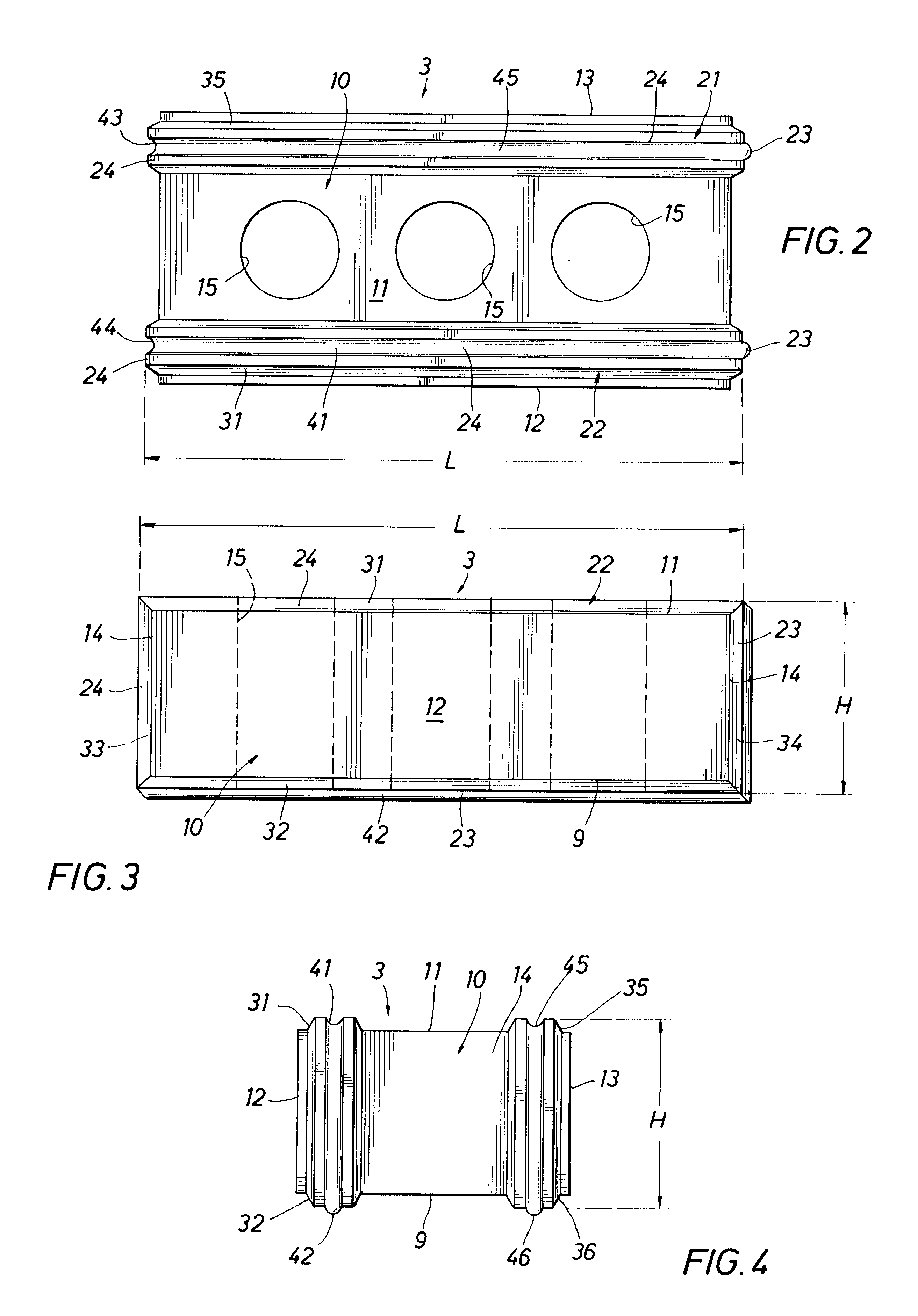
The building block unit of the present invention is self-aligning, self-leveling and self-plumbing. It lends itself to semi-skilled labor or automatic machine installation and eliminates the delay required to curing of wet mortar as in the prior art. The masonry building unit includes a block, such as a brick, and a separate mounting strip secured about the periphery of the block. The block is a rectangular parallelepiped including a pair of parallel rectangular end faces, a pair of parallel rectangular side faces, and parallel rectangular upper and lower faces. At least one mounting strip extends continuously about the periphery of the block including the pair of end faces, and the upper and lower faces. One half of the length of the mounting strip has a projection or key thereon and the remaining half of the length of the mounting strip has a groove. The grooves and projections on opposed mounting strips on adjacent blocks interfit for mounting of adjacent building units in precise horizontal layers with each horizontal layer including a plurality of building units in end to end relation. Each mounting strip has a planar surface extending in a direction parallel to the adjacent faces of the block on which the mounting strip is secured. The parallel planar surfaces on opposed mounting strips of adjacent blocks are in face to face contact with each other and superjacent building units are supported on the planar surface of subjacent mounting strips on the upper faces of the subjacent blocks.
The mounting strips are recessed inwardly from the adjacent side faces of the blocks to provide a continuous recess about the periphery of blocks positioned in horizontal layers of a vertical wall. The outer exposed perpendicular planar surfaces on opposed mounting strips of adjacent blocks are secured together with a suitable adhesive means for securing adjacent building units together. Thus, a smooth joint extends about the entire periphery of the block to provide a smooth uniform appearance between adjacent building units.

Problems solved by technology

One of the major problems associated with masonry construction is the nonuniformity of building block dimensions due to shrinkage, warping, twisting, etc.
Another major problem associated with masonry construction is the mortar materials utilized to bond the bricks or other building blocks together.
While so much depends on the quality of mortar used, mortars are typically mixed at the job site and can easily be incorrectly mixed or used beyond its useful mix life.
Thus, even though masonry construction has been utilized for centuries, there are still some inherent problems pertaining to the lack of uniformity of quality and dimensions in the brick or other building blocks and to the weaknesses associated with the mortars used therewith.

Method used


Image

  • Method for manufacturing a modular building block unit and construction therewith
  • Method for manufacturing a modular building block unit and construction therewith
  • Method for manufacturing a modular building block unit and construction therewith

Examples


Embodiment Construction

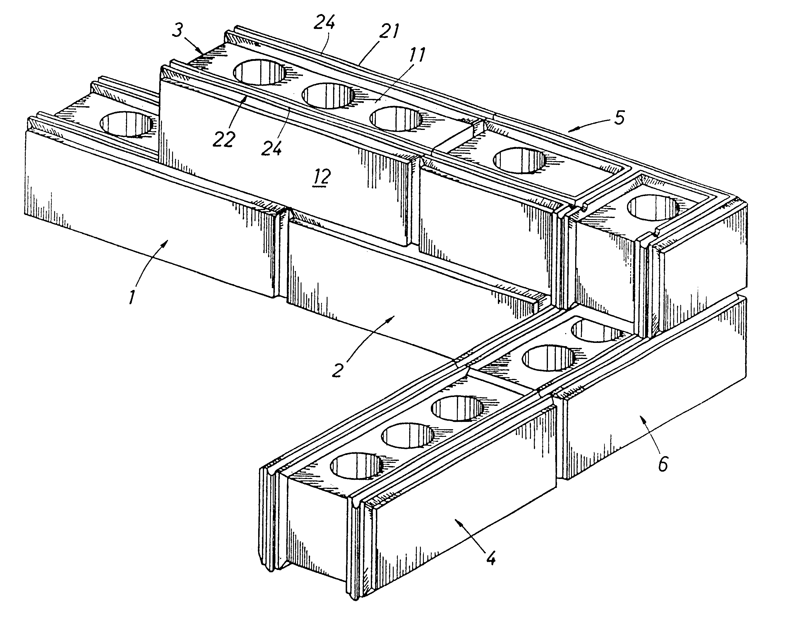
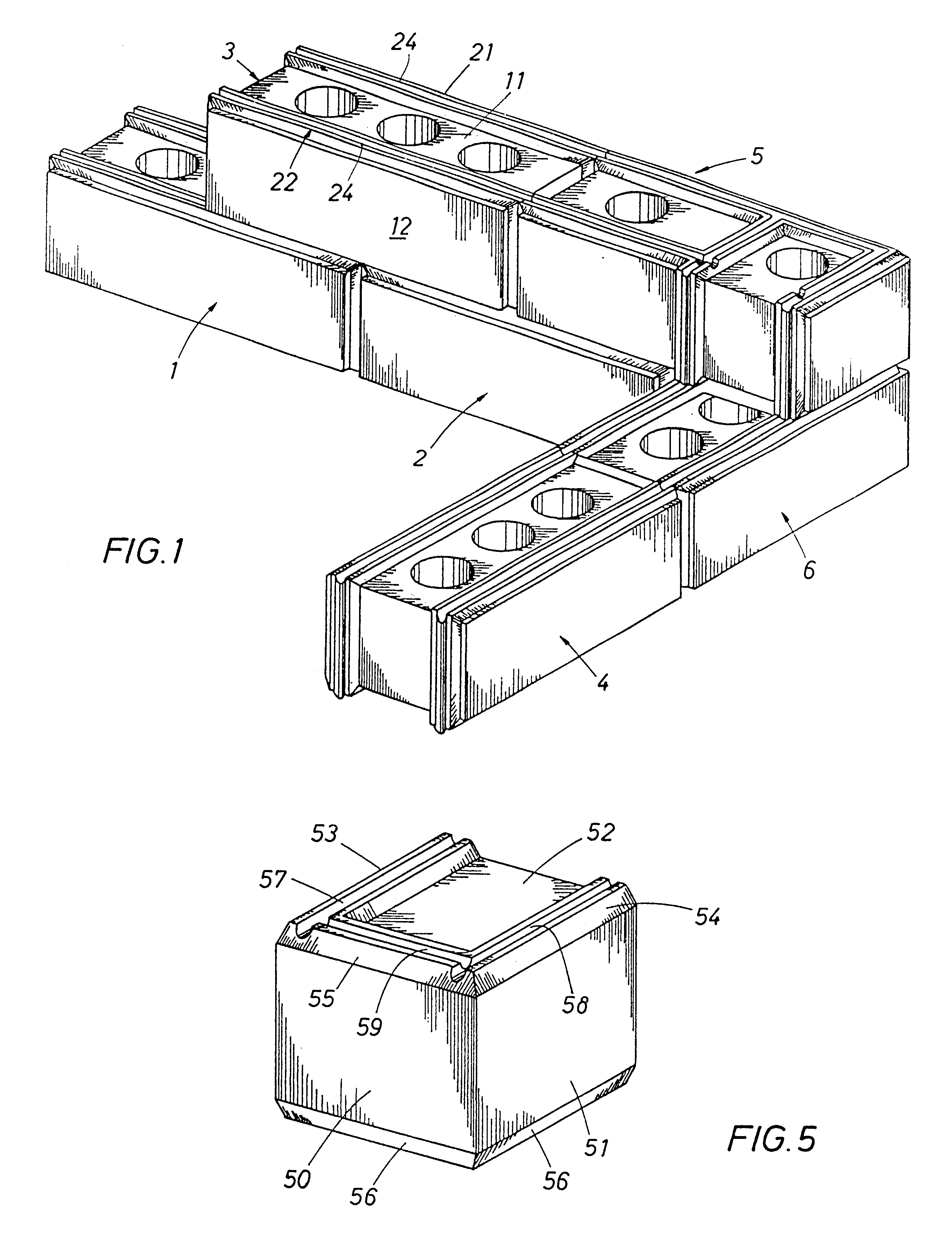
Referring first to FIG. 1 for the first embodiment of the invention, there is shown the partially constructed corner of a building or other walled structure made up of several building block units, 1, 2, 3, 4, 5 and 6. As previously mentioned, the term "building unit" or "modular building unit" refers to the building block and the mounting strip which is molded to the building block. Building block units 1, 2, 3 and 4 are referred to as running course building units. Building block units 5 and 6 are referred to as corner building block units. Both types of building block units will be more fully described hereafter.

In the exemplary embodiments, the building blocks are illustrated as bricks. However, the building blocks of the present invention can be brick, stone, concrete, glass, ceramic tile, clay tile (whether used for walls, roofs, floors, etc.) or any other type of building block which is typically joined by mortar, grout or similar materials. Thus, when the term "brick" is use...


PUM

PropertyMeasurementUnit
Currentaaaaaaaaaa
Currentaaaaaaaaaa
Currentaaaaaaaaaa

Abstract

A modular building unit (1-6, 1A) including a building block (10, 10A) having lower and upper faces (9, 9A, 11, 11A), side faces (12, 12A, 13, 13A) and end faces (14, 14A). At least the lower and upper faces are provided with mounting strips (21-24, 53A, 54A) interfit with mating mounting strips (21-24, 53A, 54A) on similar adjacent modular building units (1-6, 1A) to join the adjoining building block units (1-6, 1A) in predetermined dimensionally accurate relationships. A method of securing the mounting strips (21-24, 53A, 54A) to the building block or brick (10, 10A) and the method of interlocking and securing adjacent modular building units (1-6, 1A) to each other are disclosed. A preferred embodiment of mounting strips (53A, 54A) is shown in FIGS. 8-10. A mold (203) is shown in FIG. 12 for the preferred method of forming a building block or brick (200).

Description

1. Field of the InventionThe present invention pertains to masonry construction. More specifically, the present invention pertains to building block units, installation of building block units and methods of manufacturing and utilizing such. In particular, the present invention pertains to a unique building block unit or modular building unit in which a standard brick or other type of building block is placed in a mold and a mounting strip applied to faces of the brick or other type building block and allowed to set as an additional manufacturing step to form the building block unit.2. Description of the Prior ArtMasonry construction, one of the traditional methods of building, has been utilized for many centuries. Masonry, simply stated, is the assembly of building block units, such as bricks, stone, concrete, etc., by laying such units adjacent to each other in a composite wall, column or other structure. These units are typically joined by some type of mortar which is wet and mix...

Claims


Application Information

Patent Timeline
IPC IPC(8): E04B2/14E04B2/16E04B2/02
CPCE04B2/16E04B2002/0213
Inventor SHERWOOD, DON T.
Owner SHERWOOD DON T
Learn More