
Method of cleaning and maintaining petroleum refining plants

a petroleum refining plant and cleaning technology, applied in the direction of cleaning using liquids, other chemical processes, separation processes, etc., can solve the problems of deteriorating the thermal conductivity of agglomerated catalysts, affecting the efficiency of refining plants, and affecting the operation of continuous plants

Inactive Publication Date: 2001-08-14
NICCA CHEM COMPANY
View PDF4 Cites 22 Cited by
  • Summary
  • Abstract
  • Description
  • Claims
  • Application Information

AI Technical Summary

Benefits of technology

Specifically, it is noticed in the present invention that the catalyst is necessary to be cooled from a high temperature to a temperature capable of conducting the unloading work in order to dump out the catalyst. Accordingly, the entirety of the coating process of the catalyst, softening process of the catalyst, chemical cleaning of the equipment etc. are designed to be efficiently and effectively during the cooling time in the present invention, thereby reducing maintenance term of the plant.
In the present invention, since the process for chemically cleaning the equipment, softening the agglomerated catalyst, and coating the surface of the catalyst can be conducted in harmony in a single system, the advantages of respective process can be well performed so that the cleaning process of the process equipment and pipings, unloading process of the agglomerated catalyst, rinsing process of the process equipment and pipings can be efficiently conducted. Accordingly, the plant shutdown term can be reduced, thereby improving production efficiency.
In the above arrangement, since the cleaning fluid having cleaning and softening effect introduced into light oil circulating in the system is introduced to the catalyst agglomerated in the reactor, the catalyst can be softened to be particles, so that more complete coat can be formed on the surface of the catalyst. Accordingly, the unloading process of the catalyst can be conducted more safely. Further, since the grained catalyst has increased cooling speed, the cooling time of the catalyst can be reduced.
However, since alkali cleaning fluid and rinsing agent are used in the present invention, so-called neutralization cleaning, in which sulfide inside the equipment can be neutralized during the cleaning and rinsing of the equipment, can be simultaneously conducted. Therefore, the polythionic acid stress-corrosion cracking can be prevented when the equipment is made open.
Since the cleaning process is conducted when the catalyst is lowered to the predetermined temperature in the present invention, the cleaning fluid can be used in the most suitable condition, thereby enabling secure cleaning.
In the above arrangement, since the cleaning fluid and the first rinsing fluid is oil, the waste liquid can be re-distilled and collected as light oil, or alternatively, utilized as blend material of heavy oil. Accordingly, there is no burden of waste liquid treatment.

Problems solved by technology

Catalayst activity deteriorates during continuous plants operation due to coking, poisoning or the like.
Therefore, when thus reduced catalyst is exposed to the air for replacement, the catalyst is oxidized to generate heat, thus causing possible ignition of carbide, sulfur and the like adhered to the catalyst during operation.
Thermal conductivity of the agglomerated catalyst is greatly deteriorated and the catalyst is not sufficiently cooled during cooling process.
Accordingly, work efficiency for unloading the agglomerated catalyst is lowered, resulting in longer shutdown maintenance term.
However, since the waste water after softening the agglomerated catalyst contains compounds contaminating the environment, waste water treatment is necessary.
Further, since the catalyst inevitably contacts the air, the dumping process is likely to be dangerous.
When the contaminant is generated in piping, for example, the quality of the products deteriorates and production efficiency is lowered since the fluid flow is restricted.
In an extreme case, the line may be choked and the devices may be damaged.
When the contaminant is generated on the heat-transfer surface, excessive duty is required to the equipment to accelerate deterioration and abrasion of metal and to increase fuel cost.
Accordingly, plant shutdown term gets longer, thereby deteriorating the production efficiency.
When the equipment is made open, the iron sulfide reacts with the air to generate polythionic acid, which is thought to cause stress corrosion cracking.

Method used


Image

  • Method of cleaning and maintaining petroleum refining plants
  • Method of cleaning and maintaining petroleum refining plants

Examples


Embodiment Construction

)

An embodiment of the present invention will be described below with reference to attached drawings.

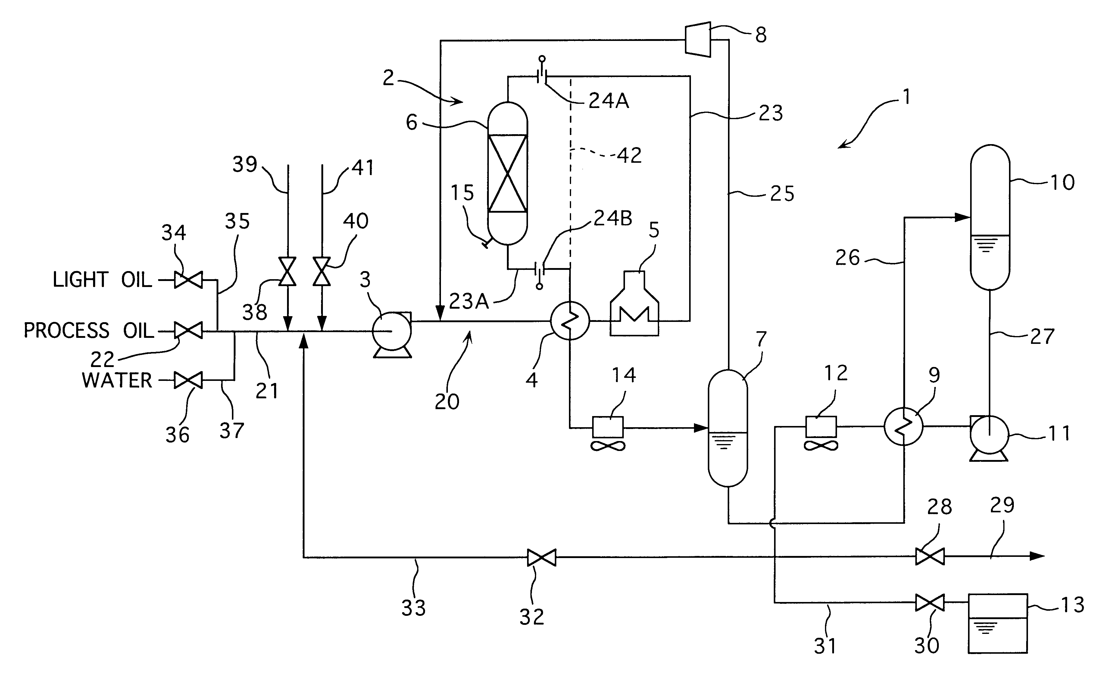
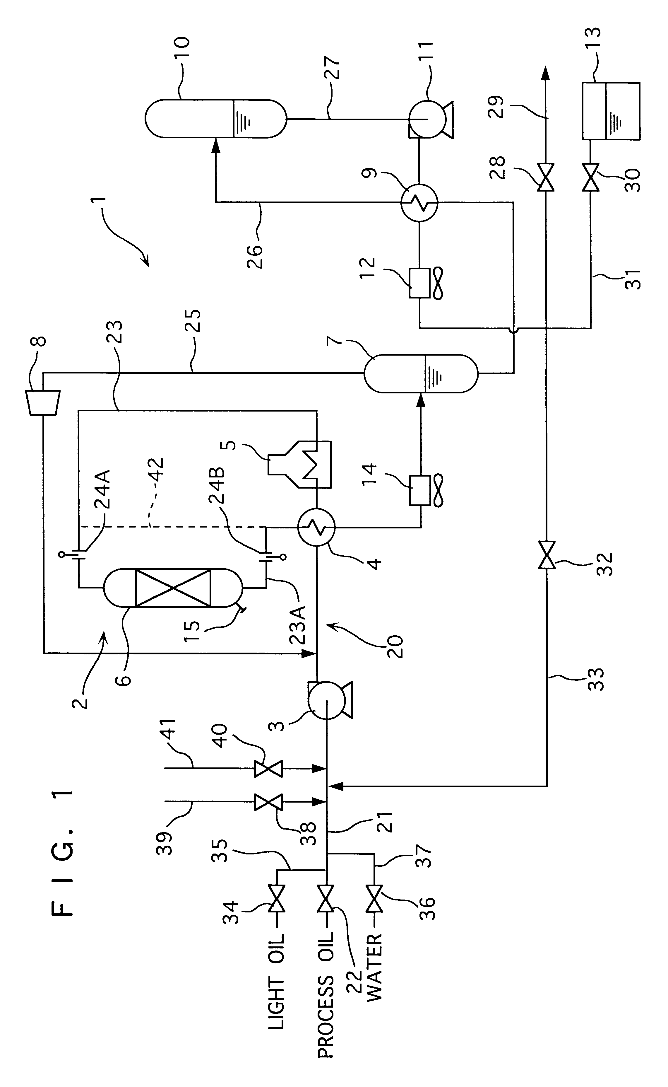
As shown in FIG. 1, a petroleum refining plant 1 to be applied with the cleaning of the present embodiment has a process equipment group 2 including reactor 6 for reacting more than one material at a predetermined temperature and pressure condition, a furnace 5 for heating the material etc. to a predetermined temperature, a separator 7 for separating vapor and liquid, stripper 10 for stripping gas dissolved in fluid, and piping for connecting respective process equipment 6, 7 etc.

Feed material supply pipe 21 of piping 20 for supplying material such as heavy oil has an on-off valve 22 and a pump 3 at an intermediate portion thereof. A heat exchanger 4 and the furnace 5 are disposed on a discharge side of the pump 3.

A flange 24A for inserting a blind to shut therefront and therebehind is provided at a midway of an outlet pipe 23 connected to the furnace 5. An end of the outlet pipe 23 i...


PUM

PropertyMeasurementUnit
Angleaaaaaaaaaa
Temperatureaaaaaaaaaa
Stress optical coefficientaaaaaaaaaa

Abstract

A repairing method of a petroleum refining plant for efficiently conducting cleaning process of process equipment and pipings, unloading process of agglomerated catalyst, rinsing work of the process equipment and the pipings, thereby reducing plant shutdown time, preventing stress-corrosion cracking by polythionic acid, improving production efficiency, ensuring work safety and reducing production cost, is provided. For the object, the repairing method of the petroleum refining plant of the present invention has a first step of cleaning the process equipment and the pipings and softening agglomerated catalyst inside the process equipment, second step of rinsing the process equipment and the pipings and coating a surface of the softened catalyst by a coating agent, and third step of dumping the coated catalyst from the process equipment and re-rinsing the process equipment and the pipings. Accordingly, respective work can be efficiently conducted, the plant shutdown time can be reduced, the stress-corrosion cracking by the polythionic acid can be prevented, and work safety, reduction of maintenance cost and improvement of production efficiency can be ensured.

Description

1. Field of the InventionThe present invention relates to petroleum refining plants. More specifically, the present invention relates to method of cleaning and maintaining a petroleum refining plant, in which process equipment such as a furnace, reactor, heat exchanger and stripper are chemically cleaned, and rinsed after a softening catalyst agglomerated in the reactor and a surface of the catalyst softened by the chemical cleaning is coated and passivated, these processes being combined and conducted simultaneously.2. Description of Related of Related ArtCrude oil is refined and various products and feed materials for chemical petroleum plant are manufactured in a petroleum refining plant, in which various catalysts are used. Catalayst activity deteriorates during continuous plants operation due to coking, poisoning or the like. Accordingly, periods repair to exchange the catalyst is necessary. The catalyst is exchanged by initially unloading the spent catalyst and subsequent load...

Claims


Application Information

Patent Timeline
IPC IPC(8): B08B9/02B08B9/08B01J8/02B01J33/00C10G17/00C11D1/12C11D1/34C11D1/52C11D7/24C11D7/26C11D7/36
CPCB08B9/08B08B9/032B01J2208/00761
Inventor KAWAKAMI, KATSUHIKOTAKANO, JUNICHIXU, GUIQING
Owner NICCA CHEM COMPANY
Learn More