
Code sequence generator in a CDMA modem

a code sequence and modem technology, applied in the field of cdma modem code sequence generators, can solve the problems of inability to track the maximum off(t), inability to know the correct pilot spreading code, and excessive time taken

Inactive Publication Date: 2001-08-07
INTERDIGITAL TECH CORP
View PDF60 Cites 187 Cited by
  • Summary
  • Abstract
  • Description
  • Claims
  • Application Information

AI Technical Summary

Benefits of technology

This approach enables high-capacity, low-interference telecommunication services by supporting multiple users with minimal bandwidth requirements, effectively handling multipath fading and increasing the overall capacity of wireless communication systems in remote areas.

Problems solved by technology

If f(t) represents the received signal waveform of the spreading code chip convolved with the channel impulse response, the shape off(t) and where its maximum occurs can change rather quickly making it impractical to track the maximum off(t).
The SU cold acquisition algorithm is used by the SU CDMA modem when it is first powered up, and therefore has no knowledge of the correct pilot spreading code phase, or when an SU attempts to reacquire synchronization with the incoming pilot signal but has taken an excessive amount of time.
Thus, it may be problematical to adjust the phase .tau.
A disadvantage of the functional is that it is ill-defined because the integrals are unbounded when noise is present.
It is, however, known in the art that coherent tracking and combining is preferred because in non-coherent tracking and combining the output phase information of each Pilot AVC finger is lost.

Method used


Image

  • Code sequence generator in a CDMA modem
  • Code sequence generator in a CDMA modem
  • Code sequence generator in a CDMA modem

Examples


third embodiment

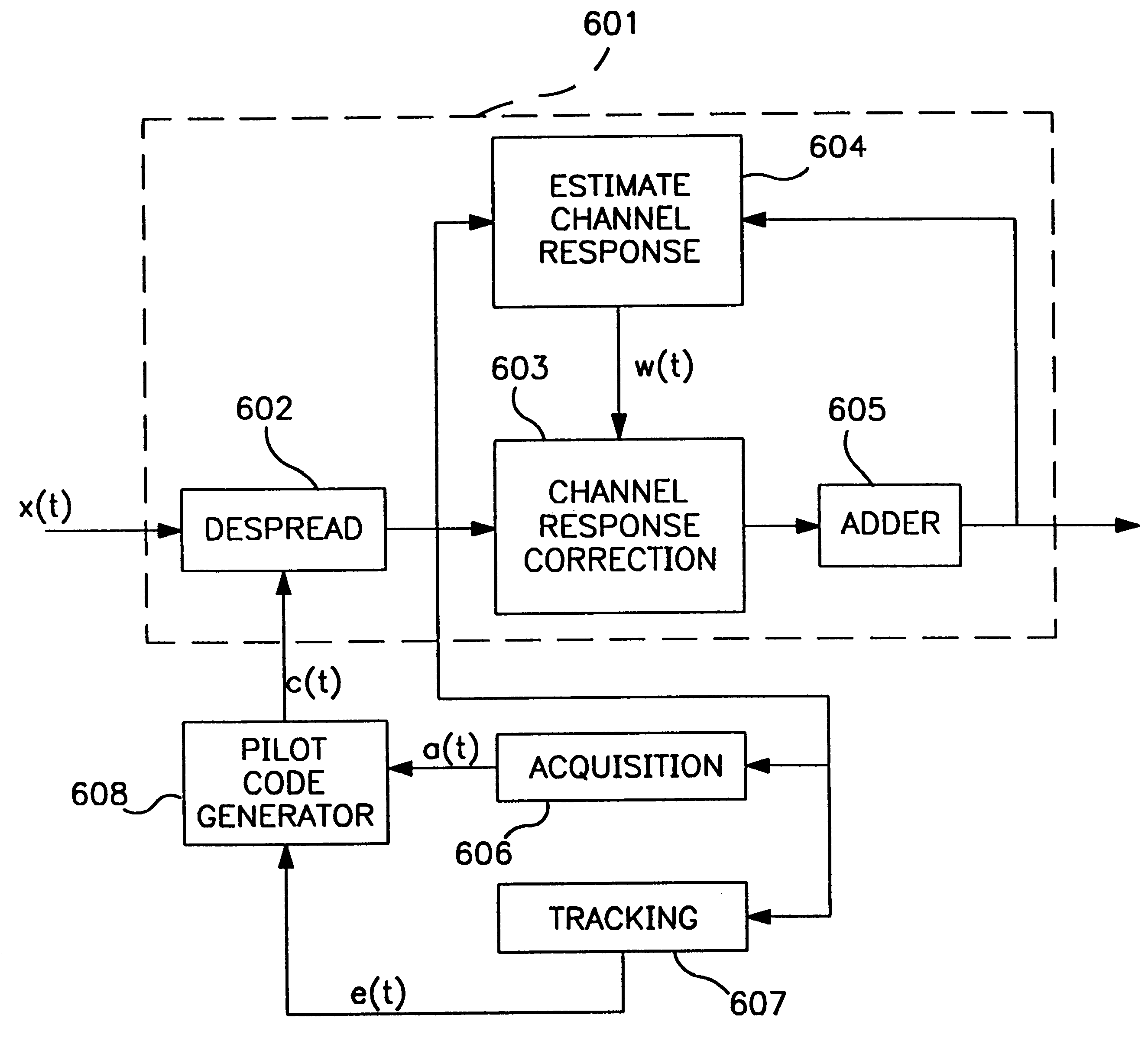
the adaptive vector correlator is shown in FIG. 8c. This embodiment uses the least mean square (LMS) statistic to implement the vector correlator and determines the derotation factors for each multipath component from the received multipath signal. The AVC of FIG. 8c is similar to the exemplary implementation of the Pilot AVC used to despread the pilot spreading-code shown in FIG. 7. The digtal phase locked loop 721 is replaced by a phase locked loop 850 having a voltage controlled oscillator 851, loop filter 852, limiter 853, and imaginary component separator 854. The difference between the corrected despread output signal dos and an ideal despread output is provided by adder 855, and the difference signal is a despread error value ide which is further used by the derotation circuits to compensate for errors in the derotation factors.

In a multipath signal environment, the signal energy of a transmitted symbol is spread out over the multipath signal components. The advantage of mult...


PUM


Abstract

A CDMA modem includes a modem transmitter having: a code generator which provides an associated pilot code signal and which generates a plurality of message code signals: a spreading circuit which produces a spread-spectrum message signal by combining each of the information signals with a respective one of the message code signals; and a global pilot code generator that provides a global pilot code signal to which the message code signals are synchronized. The CDMA modem also includes a modem receiver having an associated pilot code generator and a group of associated pilot code correlators for correlating code-phase delayed versions of the associated pilot signal with a receive CDM signal to produce a despread associated pilot signal. The code phase of the associated pilot signal is changed responsive to an acquisition signal value until a pilot signal is received. The associated pilot code tracking logic adjusts the associated pilot code signal in phase responsive to the acquisition signal so that the signal power level of the despread associated pilot code signal is maximized. Finally, the CDMA modem receiver includes a group of message signal acquisition circuits, each including a plurality of receive message signal correlators which correlate respective local received message code signal to the CDM signal to produce a respective despread received message signal.

Description

Providing quality telecommunication services to user groups which are clasified as remote, such as rural telephone systems and telephone systems in underdeveloped countries, has proved to be a challenge over recent years. The past needs created by these services have been partially satisfied by wireless radio services, such as fixed or mobile frequency division multiplex (FDM), frequency division multiple access (FDMA), time division multiplex (TDM), time division multiple access (TDMA) systems, combination frequency and time division systems (FD / TDMA), and other land mobile radio systems.Often, these remote services are faced with more potential users than can be supported simultaneously by their frequency or spectral bandwidth capacity.Recognizing these limitations, recent advances in wireless communications have used spread spectrum modulation techniques to provide simultaneous communication by multiple users. Spread spectrum modulation refers to modulating a information signal w...

Claims


Application Information

Patent Timeline
Patent Type & Authority Patents(United States)
IPC IPC(8): H04J13/00H04L27/233H04L25/02H04J13/02H04B1/707H04L1/00H04B7/005H04J13/04H04B7/26H04L27/20H04L27/00G06F13/374H03K3/84H03H17/02H03H17/06H04B1/7075H04B1/7077H04B1/708H04B1/7085H04B1/709H04B1/7093H04B1/711H04B1/7115H04B1/712H04B7/216H04B15/00H04B17/00H04J11/00H04J13/10H04J13/12H04J13/16H04K1/00H04L5/14H04L7/00H04L7/033H04L27/30H04N1/333H04W52/04H04W52/14H04W52/24
CPCH04B1/707H04B1/70753H04B1/70754H04B1/70755H04B1/70758H04B1/708H04B1/7085H04B1/709H04B1/7093H04B1/711H04B7/2637H04J13/00H04J13/10H04J13/107H04L1/004H04L1/0042H04L1/0059H04L25/0212H04L27/206H04L27/2332H04W52/04H04W52/08H04W52/143H04W52/24H04W52/241H04W52/245H04W52/262H04W52/322H04W52/325H04W52/343H04W52/346H04W52/50H04W52/52H04B1/7075Y02B60/50H04B1/7115H04B1/712H04B7/264H04B2201/70701H04B2201/70702H04B2201/7071H04J13/004H04J13/0048H04J13/0077H04J13/12H04J2013/0037H04L1/0001H04L1/0054H04L2027/003H04L2027/0053H04W52/146H04W52/247H04W52/26H04W52/36H04W52/44H04W52/54H04W52/60G06F13/374H03H17/0226H03H17/06H04B1/7077H04B7/2628H04B2201/70703H04B2201/70707H04J13/16H04L1/0047H04L5/1446H04N1/00912H04N1/3333H04N2201/3335H04W52/367Y02D10/00
Inventor LOMP, GARYOZLUTURK, FATIHSILVERBERG, AVI
Owner INTERDIGITAL TECH CORP
Learn More