
Sliding bearing having multilayer lead-free overplate and method of manufacture

a multi-layer, lead-free technology, applied in the direction of connecting rod bearings, mechanical equipment, rotary machine parts, etc., can solve the problems of increasing the potential for bearing fatigue, the cost of conformability and embeddability characteristics, and the increase of the cost of bearings

Inactive Publication Date: 2001-07-31
FEDERAL MOGUL CORP
View PDF17 Cites 18 Cited by
  • Summary
  • Abstract
  • Description
  • Claims
  • Application Information

AI Technical Summary

Benefits of technology

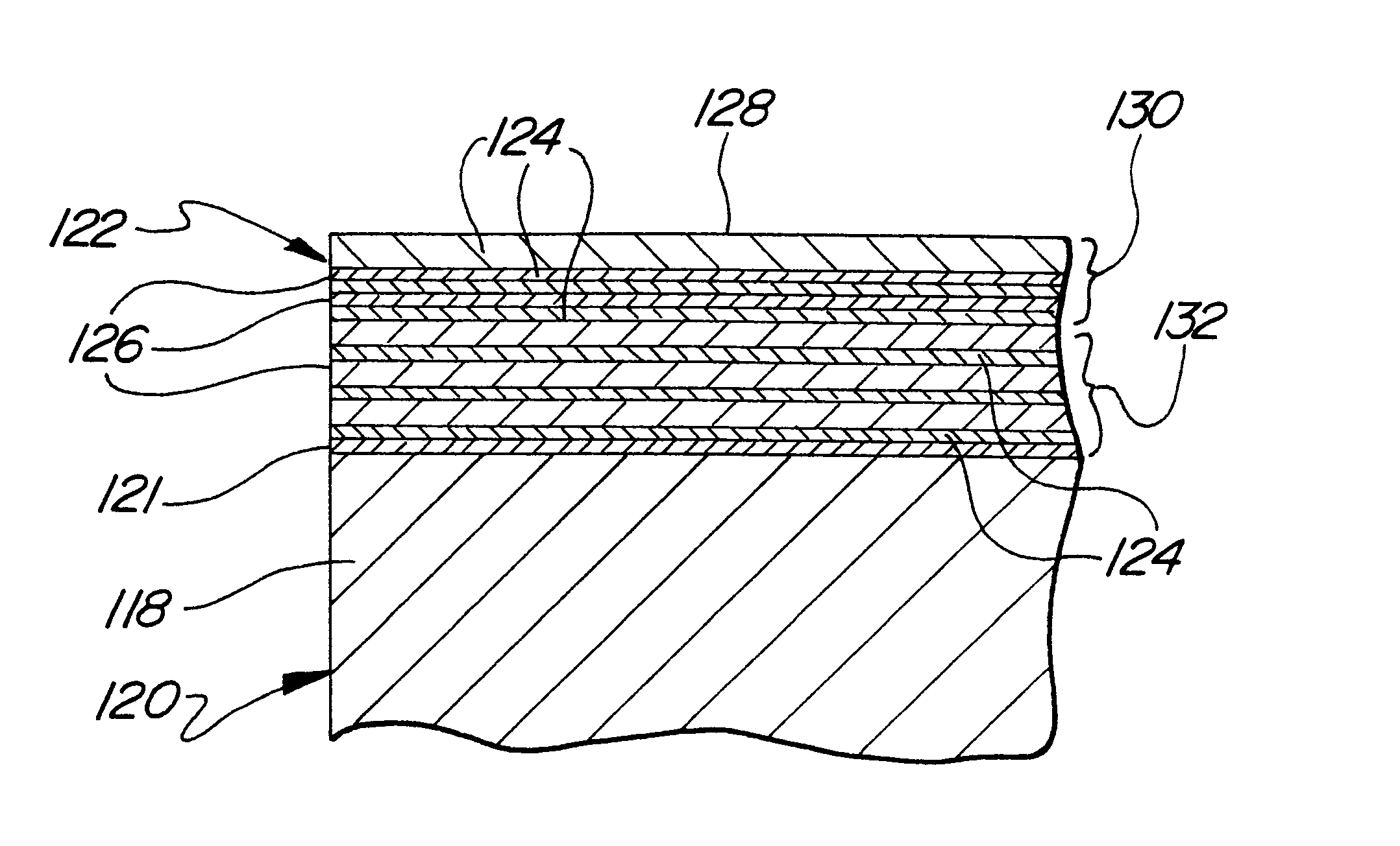
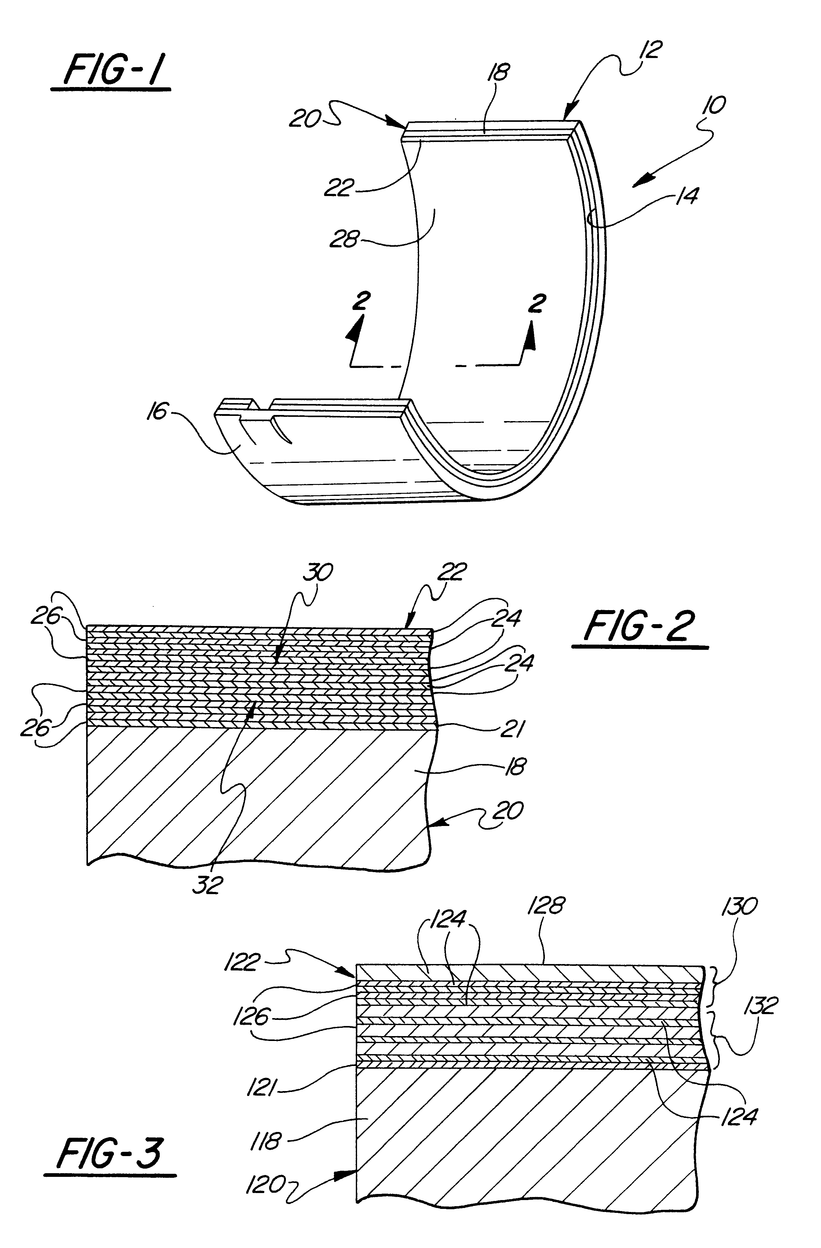
The multilayer overplate of the invention has the advantage of providing a composite overplate for a sliding bearing having good fatigue resistance as well as good conformability and embedibility characteristics using lead-free metal layers. By controlling the selection of material and the relative thicknesses of the multiple layers of the lead-free overplate, the invention enables a controlled hardness gradient to be developed in the overplate, which further enhances the above properties. According to a particular embodiment of the invention, the alternating soft and hard layers have varying relative thicknesses such that the overall macro hardness of the overplate is softer adjacent the top running surface of the overplate and is harder near the bottom of the overplate adjacent the bearing liner.
The use of lead-free materials further has the advantage of eliminating from the overplate the presence of heavy metals, and in particularly lead, which is beneficial from a manufacturing, use and reclamation stand point.

Problems solved by technology

However, as the output and efficiency of engines continually increases, so does the dynamic loads placed on the crank shaft and connecting rod bearings, increasing the potential for bearing fatigue.
While greater fatigue resistance can be achieved by simply decreasing the thickness of the conventional single layer lead-tin-copper overplate to load the 25 .mu.m thickness, it is at the cost of the conformability and embedibilty characteristics.

Method used


Image

  • Sliding bearing having multilayer lead-free overplate and method of manufacture
  • Sliding bearing having multilayer lead-free overplate and method of manufacture

Examples


Embodiment Construction

multilayer sliding bearing constructed according to the invention is generally shown at 10 in FIG. 1 and is of the type having a generally semi-circular configuration commonly known in the art as half bearings, plain bearings, sliding bearings, journal bearings, engine bearings, and the like having a rigid metal backing 12 fabricated preferably of steel formed to a semi-circular strip configuration having a concave inner surface 14 and a convex outer surface 16. The convex outer surface 16 is adapted for seating in a mating concave support structure, such as an engine block or connecting rod, for journaled support of a rotating shaft, such as a crank shaft of an internal combustion engine. The term multilayer bearing is understood to include within its scope multilayer bushings.

A liner of metallic bearing metal 18 is formed on the concave surface 14 of the backing 12 and may be fabricated of conventional materials including copper-lead or aluminum alloys which may be cast or otherwi...


PUM

PropertyMeasurementUnit
Thicknessaaaaaaaaaa
Hardnessaaaaaaaaaa

Abstract

A multilayer engine bearing (10) includes a steel backing (12) having a liner (18) of bearing metal of either copper-lead or aluminum alloys formed on the backing (12) to define a base lining member (20) of the bearing (10). A multilayer overplate (22, 122) is formed on the base lining member (20,120) and includes multiple lead-free soft layers (24,124) separated by lead-free hard layers (26,126). The relative thicknesses of the overplate layers may be controlled to provide a macro hardness gradient across the thickness of the overplate (122) such that, for example, the overplate (122) may be softer near its top region (130) as compared to its bottom region (132).

Description

1. Technical FieldThis invention relates to multilayer sliding bearings of the type having a metal backing, a liner of bearing metal and a relatively soft metallic overlay.2. Related Prior ArtMultilayer sliding bearings are typically used in high-load engine applications for journaling the crankshaft, connecting rods, and the like and include a rigid metal backing of steel on which a lining of bearing metal of either copper-lead or aluminum alloy is applied, over which a running layer of a relatively softer metal is overplated usually in the form of a single layer of lead-tin-copper alloy having a thickness of about 25 .mu.m. A nickel diffusion barrier or copper bonding layer is often interposed between the lining and overplate to prevent the tin of the overplate from diffusing into the bearing liner. As a final step, the bearing is typically coated with a micro-thin layer of tin or lead-tin flash plating, giving the bearing a bright, aesthetically pleasing appearance and providing ...

Claims


Application Information

Patent Timeline
IPC IPC(8): F16C33/14F16C33/04F16C9/00F16C9/04F16C33/12C25D7/00
CPCF16C9/04F16C33/14F16C33/124Y10S384/912Y02T10/865F16C2223/70F16C2240/60F16C33/12
Inventor BANK, BRIAN L.TOTH, JAMES R.
Owner FEDERAL MOGUL CORP
Learn More