
Gas combustor and combustor system for combustion of smoke, off gases and other emissions

Inactive Publication Date: 2001-07-17
INDEPENDENT STAVE
View PDF6 Cites 11 Cited by
  • Summary
  • Abstract
  • Description
  • Claims
  • Application Information

AI Technical Summary

Benefits of technology

As used for combustion of gaseous, smoky emissions and other emission products, constructions and methods of the presently claimed invention are of special utility and economical suitability for efficiently burning emissions such as charcoal kiln emissions in situations where other processes and apparatus have produced gases which are amenable to further combustion and which by combustion at relatively high temperatures and with desirably high dwell times may be rendered may be converted to a safer state or effectively destroyed.
The invention also relates to the provision of such systems and combustors of high efficiency and flexibility, and particularly operating over a wide dynamic range.
The presently inventive combustors and combustor systems have advantageous intrinsic capability for being scaled to emission combustion requirements, as according to the intended mode of usage and industry segment in which the combustors are to serve. So also, combustor systems of the invention are advantageously and readily able by design for configuration appropriate for use at sites having distributed kiln or other emission sources. The new combustor systems may thus adapt to the site layout, spacing and topology of industrial installations which they are intended to serve.
A further advantage of the inventive combustors and combustor systems is their use of electronic controls using programmable logic controllers, for achieving precise, efficient, safe and reliable control and operation in all modes of usage.
In addition, burners of the present invention are economical in construction and operation.

Problems solved by technology

In burners useful for burning such materials, there has been insufficient emphasis on achieving efficiency and flexibility which can result from achieving a high turndown ratio (which may for convenience be abbreviated "TDR"), which is the maximum firing rate of the burner divided by the minimum firing rate of the burner.
Prior constructions have not achieved sufficiently high TDRs.
If the use of a burner having a limited TDR requires that burner operation be terminated if off-gas supply rates are insufficient to achieve the minimum firing rate of the burner, utility of the burner will be undesirably limited.
But, on the other hand, if a burner is designed for burning emissions at low feed rates, its output may be insufficient to handle high feed rates when wood products to be combusted are being produced at high volumes.
Present burners in the wood products industries have not met the needs for these kinds of combustion, and have not achieved satisfactory TDR and efficiencies for acceptable usage in the wood products industries.
The problem of emission products control at a charcoal kiln facility is compounded by the disparate, random, distributed or otherwise site-specific location of the multiple kilns, each kilns or arrays of kilns being a separate and distinct source of emission products.

Method used


Image

  • Gas combustor and combustor system for combustion of smoke, off gases and other emissions
  • Gas combustor and combustor system for combustion of smoke, off gases and other emissions
  • Gas combustor and combustor system for combustion of smoke, off gases and other emissions

Examples


example 1

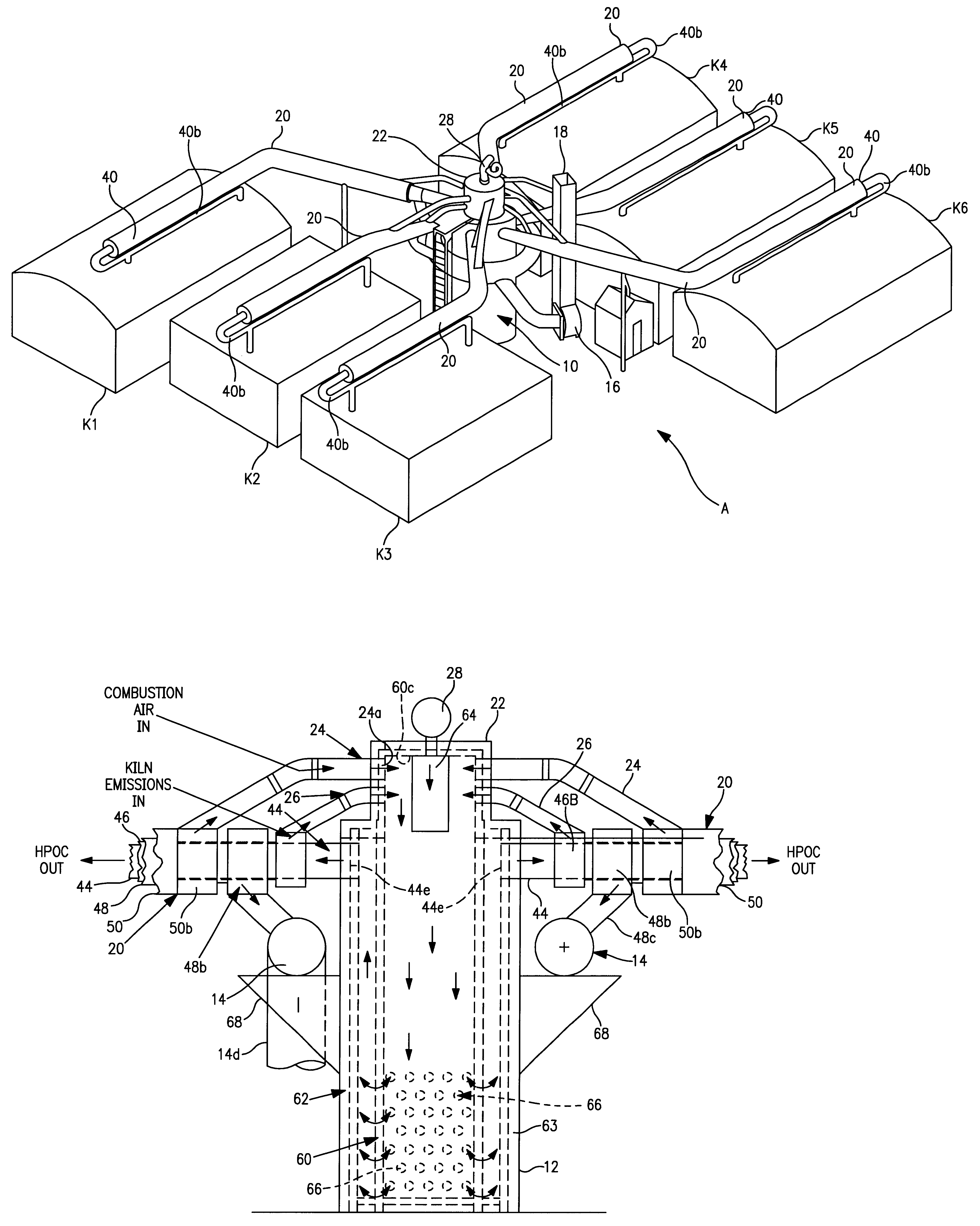
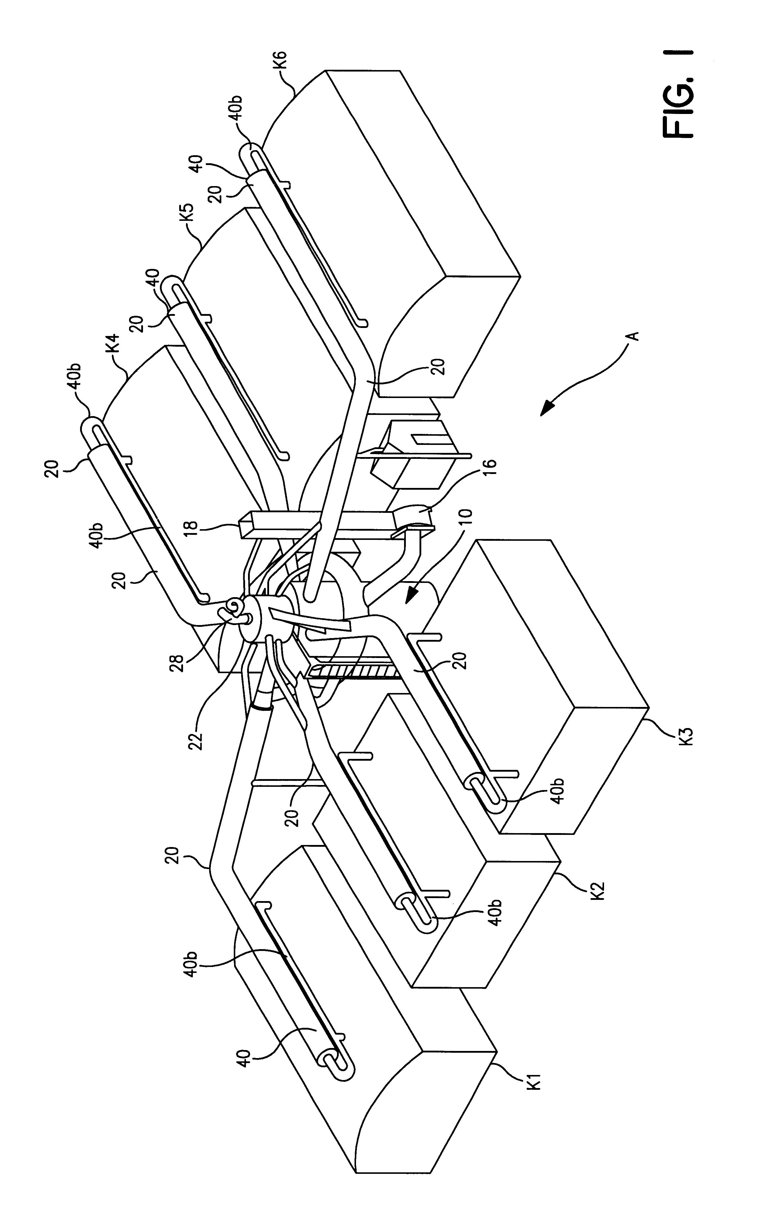
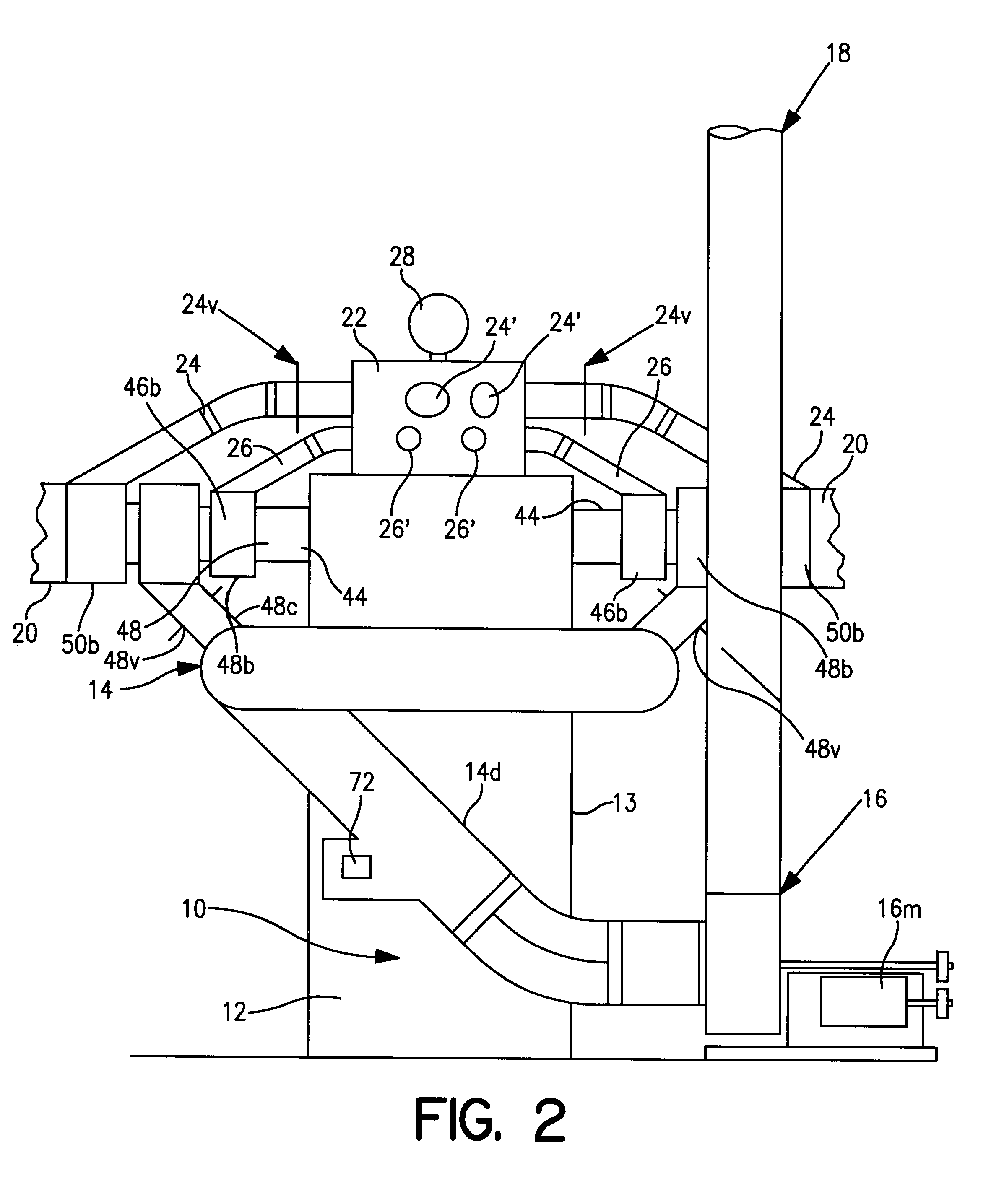
A practical combustor system having a combustor configured generally in accordance with the illustrations shown for combustor 10 is constructed using materials and features described above. It has representative dimensions as follows: Housing 12 has an overall height of about 27 ft., not including additional vertical projection of burner 28. Apertures 66 occupy about 30% of the lower third of inner heating chamber 60. Representative The diameter of apertures 66 is 6.5 in., as compared to a representative inside diameter of about 5 ft. for inner heating chamber 60 and an outer diameter of about 10 ft. for housing 12. The spacing between the inner wall of outer heating chamber 62 and outer wall of inner heating chamber 60 representatively may exceed 1 ft. Wall thickness of the inner and outer heating chambers may be of the order of 0.5 ft. The overall height of the outside walls of outer heating chamber 62 may be about 22 ft. Typical length of any of heat exchangers 20 may be at least...


PUM


Abstract

A combustor system provides high temperature, high-dwell combustion of emission products, as from charcoal kilns, with inner and outer combustion chambers. Multiple inlets receive emission products from multiple heat exchangers omnidirectionally extending for continuous heat exchange connection between the combustor and emission sources. Hot products of combustion are delivered to each heat exchanger, each with multiple ducts in mutual heat exchange relationship including at least a hot products of combustion duct for receiving at the proximal end hot products of combustion from an outlet of the outer chamber, and conveying the hot products of combustion to the distal end at a respective emission source, an emissions inlet duct for receiving emission products at the distal end from the emission source, and a return products of combustion duct for receiving at the distal end the hot products of combustion and returning them to the combustor. The heat exchanger arrangement is such that the hot products of combustion duct and the return products of combustion duct cause heating of the emission products by the heat exchange relationship. A combustion air intake passage provides intake of combustion air for each heat exchanger, which mixes in the combustion chamber with the emission products. Combustion products pass cyclonically from the inner chamber and then by reversal of direction, i.e., from downward to upward, through a concentric outer chamber, to create hot products of combustion which exit into the heat exchangers.

Description

The invention relates to improvements of the apparatus and methods of the present inventors set forth in provisional patent application Ser. No. 60 / 095,054 filed Aug. 3, 1998, entitled COMBUSTORS AND BURNERS WITH HIGH TURNDOWN RATIO, incorporated herein by reference, continued preservation of which is requested.The invention is in the field of industrial burners, combustors and incinerators and, more particularly, relates to a new combustor and combustor system for combustion of smoke and other combustible off-gases and other emissions produced in the operation of charcoal kilns and other processes, as in wood products manufacturing or processing operations.Charcoal is made by both continuous and batch processes which carry out partial combustion of wood, e.g., hardwood and / or wood waste, sawdust, agricultural products, bagasse, biomass, poultry waste, and other mixtures of various carbonaceous or cellulosic materials. A well-known example of batch process for charcoal manufacture i...

Claims


Application Information

Patent Timeline
IPC IPC(8): F23G7/06F23G5/32F23G5/18F23G7/08F23C3/00F23G5/14
CPCF23C3/006F23G5/18F23G7/085F23G7/066F23G5/32
Inventor BOSWELL, JOHN J.EICHMEYER, DALE R.
Owner INDEPENDENT STAVE
Learn More