
Substrate handling method and apparatus, and attractive force inspection method and apparatus used therewith

Inactive Publication Date: 2001-07-03
PANASONIC CORP
View PDF5 Cites 16 Cited by
  • Summary
  • Abstract
  • Description
  • Claims
  • Application Information

AI Technical Summary

Benefits of technology

Here, as described above, when the substrate is pushed up and released from the substrate holder, data related to the attractive force between the substrate holder and the substrate is detected, and when the detected attractive force is greater than a predetermined value, push-up is controlled so that the substrate can be pushed up and released from the substrate holder at proper timing in accordance with the residual state of the attractive force between the substrate holder and the substrate. By this method, substrate damage is eliminated, and transport trouble, such as the inability to transport, bad transport attitude, droppage, and improper loading at the next process, can be avoided when transporting the substrate to the next process, thereby enhancing reliability. Moreover, since release timing becomes the minimum time required, loss time can be eliminated, and throughput efficiency can be enhanced.
In particular, when the substrate is pushed up from the substrate holder, data related to the attractive force of the substrate holder on the substrate at the push-up thereof is detected based on the push-up load, and in case the attractive force is detected to be greater than a predetermined value, push-up operation is stopped. Thereafter, push-up and stopping are repeated until the attractive force drops below the predetermined value, only when the substrate is completely released. In this way, each time the substrate is pushed up and stopped while controlling the push-up of the substrate in accordance with the attracted state of the substrate to the substrate holder, the contact portion of the substrate with the substrate holder is separated first slightly, after which, as this separating portion gradually expands, the attractive force of the substrate holder decreases, enabling the substrate to be gently released yet more quickly, and further enhancing throughput efficiency.
If the detector for detecting as attractive force-related data the push-up load exerted by the push-up system is provided part way along the push-up force transfer system of the push-up system, and connected onto the drive force transfer axis of the driver, the operation, in which the push-up system is pushed up by the driver, acts with precision on the detector, enabling the push-up load at that time to be detected accurately.
By providing a construction such that the substrate holder is disposed inside the vacuum chamber, which places the process work area in a vacuum state, whereas the detector is provided on the atmosphere side outside the vacuum chamber, thereby being located more than a certain distance away from the substrate holder and not electrically connected thereto, the detector will not be affected by the vacuum state, the difference in pressure inside and outside the vacuum chamber, nor the electrical effects from the substrate holder side, making possible more precise detection. And being outside the vacuum chamber facilitates characteristic adjustments and repairs, replacement and other such maintenance.

Problems solved by technology

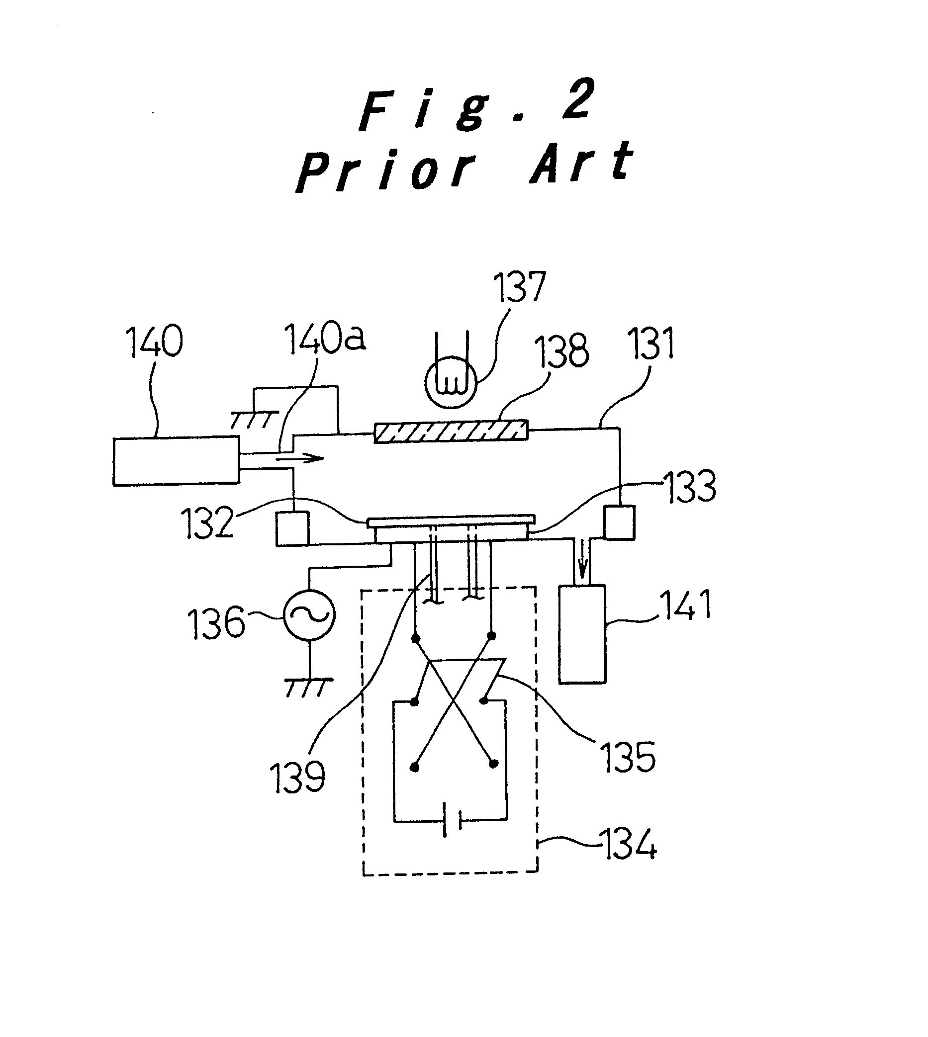
However, with the system in which charge removal is performed by reversing the polarity of the applied direct current voltage to the electrostatic attraction electrode 133 following plasma processing, it is difficult to remove completely but not excessively the residual electric charge.
Further, transport trouble, such as the inability to transport, bad transport attitude, droppage, and improper loading at the next process, can occur when the substrate 132 is transported to the next process, thus lowering reliability.
Conversely, with the charge removing plasma process, because data related to the electrostatic attractive force is not directly monitored, the plasma discharge duration is set to last somewhat longer, causing a drop in throughput efficiency.
Moreover, with charge removing plasma processing which is performed inside the vacuum chamber, dust is generated from the vacuum chamber caused by micro-sputtering, and there occurs impurities contamination and dust generation from the electrode material, which also leads to reduced quality and reliability.

Method used


Image

  • Substrate handling method and apparatus, and attractive force inspection method and apparatus used therewith
  • Substrate handling method and apparatus, and attractive force inspection method and apparatus used therewith
  • Substrate handling method and apparatus, and attractive force inspection method and apparatus used therewith

Examples


Embodiment Construction

Preferred embodiments of the present invention will be described hereinbelow with reference to the accompanying drawings.

The substrate handling method and apparatus therefor according to this embodiment described below are one example of when a substrate to be processed is a silicon wafer, and reactive ion etching-type plasma dry etching is performed thereon. It should be noted, however, that the present invention can be applied in common to all sorts of substrate handling, in which problems associated with a push-up operation when separating, from the substrate holder, the substrate that keeps being attracted to the substrate holder during or following the processing, must be addressed.

A wafer 2 handling method is described by referring to FIG. 1 which shows the apparatus of this embodiment. A wafer 2 is held on an electrostatic attraction electrode that serves as the substrate holder 3 of an electrostatic attraction-type plasma apparatus, and after being furnished with a variety o...


PUM

PropertyMeasurementUnit
Vacuumaaaaaaaaaa
Attractive forceaaaaaaaaaa

Abstract

Data related to an attractive force between a substrate holder 3 and a substrate 2 is detected when pushing up and releasing the substrate 2 from the substrate holder 3, and when the attractive force is detected to be greater than a predetermined value, the push-up operation is regulated by a controller 18.

Description

1. Field of the InventionThe present invention relates to a substrate handling method and apparatus, and an attractive force inspection method and apparatus utilized therewith, used in a state wherein an attractive force is generated between a substrate and a substrate holder when the substrate as an object to be processed is held on the substrate holder where various processing is performed, for example, during plasma processing utilized in thin film formation, micro-fabrication and the like in the manufacture of semiconductor devices, liquid crystal display panels, solar cells and the like.2. Description of the Related ArtTo enhance device functionality, and reduce the processing costs thereof, efforts have been energetically undertaken in recent years to make plasma processing apparatus more accurate and faster, and to handle larger diameter process objects, while reducing damage. Of these, control of substrate temperature to achieve inplane uniformity and precision is required i...

Claims


Application Information

Patent Timeline
IPC IPC(8): H01L21/683H01L21/67H01L21/00H02N13/00
CPCH01L21/67253H02N13/00H01L21/6833Y10T279/23H01L21/68
Inventor MATSUDA, IZURUHARAGUCHI, HIDEOYAMAMOTO, SHIGEYUKI
Owner PANASONIC CORP
Learn More