System for enhancing a video presentation

Inactive Publication Date: 2001-06-26
FOX SPORTS PRODN
View PDF71 Cites 86 Cited by
  • Summary
  • Abstract
  • Description
  • Claims
  • Application Information

AI Technical Summary

Benefits of technology

FIG. 2 shows a cutaway plan view of puck 10. All twelve diodes (28, 30, 32, 34, 36, 38, 40, 42, 44, 46, 48 and 50) along outer circumference 16 can be seen. Each diode is housed in a bore approximately the size of the diode. Inside of the puck is a recess 60 which receives printed circuit board 62. Mounted on printed circuit board 62 are electronics and a battery 64. Wires 28w, 30w, 32w, 34w, 36w, 38w, 40w, 42w, 44w, 46w, 48w and 50w run from printed circuit board 62 to the diodes. Battery 64 can be more than one battery vertically stacked in the center of printed circuit board 62. The battery is a lithium battery which handles cold temperatures well and has high current capability. It is important that the electronics operate sufficiently under cold temperatures because hockey pucks are traditionally frozen prior to use during a hockey game. High current capability is also important so that the infrared emitting diodes can be driven with the high current to maximize the intensity of the infrared signal. Battery 64, printed circuit board 62 and the infrared emitting diodes are held in place using filler materials (microspheres) and a flexible epoxy, for example, DP190 by 3M. Additionally, any gaps in recess 60 not occupied by the electronics could be filled with epoxy to help secure the electronics and to maintain the pucks hardness and elasticity.
The above described radar base unit is able to determine the distance from the base unit to the puck. Thus, a sphere can be drawn with the center of the sphere being the base unit and the radius of the sphere being the distance from the base unit to the puck. The puck's three-dimensional location can be determined using three base units. If spheres are drawn for each base unit, the three spheres will intersect at two points. One of these points is in the field of play and represents the three-dimensional position of the puck. The second point is an unrealistic location and is discarded. Once the puck's location is determined, a system can enhance the presentation of the puck in a manner similar to that described above.

Problems solved by technology

Because of the size and speed of some objects and the distance of the television camera from the playing field, some objects at a sporting event are hard to see on a television screen.
However, the limited field of view of a zoomed camera prevents the object from being viewed in relation to the playing field and prevents the viewer from seeing other objects that are part of the sporting event.
Additionally, even with zoom lenses some objects remain difficult to see on television.
For example, television viewing of a hockey game is hampered by poor visibility and distortion of the hockey puck.
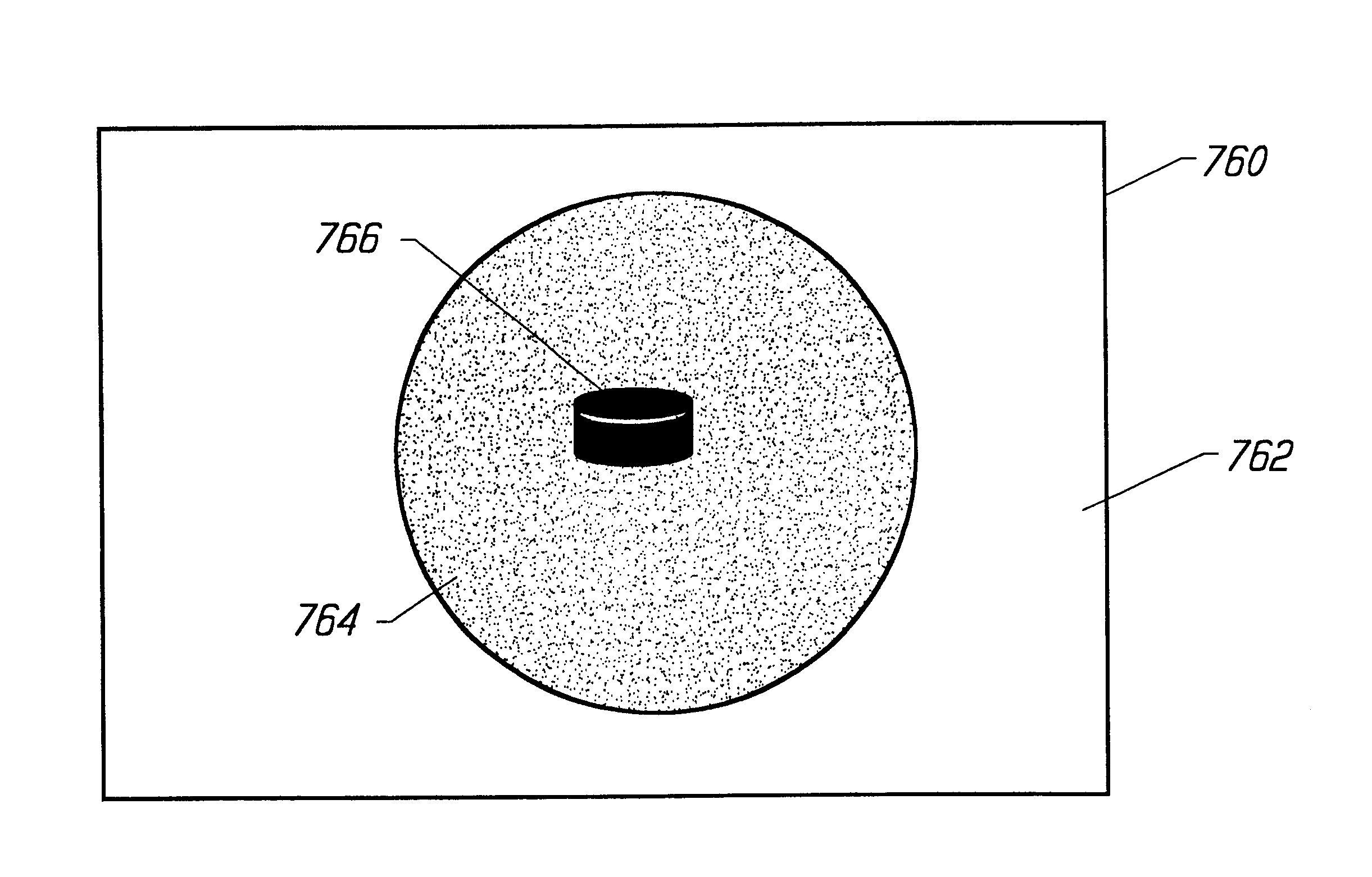
As a result, it is difficult to follow the puck from player to player, and it is especially difficult to follow the puck as it is shot toward the goal.
Because viewers cannot follow the puck, they do not sustain interest in the game.
In golf and baseball it is hard to see the ball when the ball is hit in the air for a long distance (e.g. a home run in baseball or a tee shot in golf).
Such a view of the ball does not give the viewer a true perspective of the ball's path.
That is, the viewer cannot determine how far the ball was hit or where the ball is in the relation to the playing field.
However, such a zoom-out will make the ball difficult or impossible to see.
Other sporting events present similar visibility problems.
In some systems, however, the superimposed graphics can have the effect of hiding the actual image of the object which detracts from some viewer's enjoyment of the broadcast.
The disadvantage of using two sensors in master and slave configuration is the additional cost and complexities of integrating a second sensor.
Many arenas do not allow photographers to use flashes on their cameras in order to prevent impairing the players' vision from random flashes.
Certain pixels are so dim that they cannot be valid data.
In performing the steps of sensing infrared data, capturing video and enhancing a video frame, error can be introduced due to distortion in the broadcast camera's lens and / or the sensor's lens.
The radius should be big enough to allow the system to function, but small enough so that improper data is thrown out.
Each time the system is set up, a user may need to use trial and error to determine the proper radius.
In reality, the motion of the camera point of view (POV) is much more complicated with offsets caused by the kinematics of the tripod and the motion of the optical POV along the camera's optical axis due to lens characteristics.
If the camera is behind the boards, then the boards will obstruct the camera's view of the puck.
However, the particular broadcast camera whose view is obstructed by the boards will not be able to see the puck.
Since these sensors are rigidly mounted, they cannot be panned and tilted.
The measured zoom can have errors due to bias, gain or focal length.
If the system halts the randomization process, then the system stops and reports the error to an operator.
By the term "mis-registered" is meant that something happens such that data from that sensor cannot be properly interpreted.
For example, the sensor could be bumped such that its orientation is changed and, therefore, matrix (J) can no longer be used to accurately transform data from the sensor.
Furthermore, during the live event there may not be access to the playing field (or ice) for registration purposes.
If a sensor is not being used, then it may be mis-registered.
That is, the sensor is still being operated and used to collect data; however, its data is not being used for its intended purpose.
Data is not saved for every frame because too much data will accumulate.
On the other hand, adding beacons to the hockey rink could be logistically difficult and costly.
For example, the wiring can be costly, time consuming and annoying to the fans at the arena.
These breaks are considered to be part of the live event and, usually, are not long enough to perform the entire registration process.
Since there are no clusters from other infrared sensors, a three dimensional location of the puck cannot be determined.
In the hockey application, the energy scattered from a conventional puck can be lost in all the undesired back scattered energy (clutter) from the players, the rink, the building, etc.
Second, the repeater electronics are entirely confined within the rubber of the puck.

Method used


Image

  • System for enhancing a video presentation
  • System for enhancing a video presentation
  • System for enhancing a video presentation

Examples


Embodiment Construction

has been presented for purposes of illustration and description. It is not intended to be exhaustive or to limit the invention to the precise form disclosed, and obviously many modifications and variations are possible in light of the above teaching. The described embodiments were chosen in order to best explain the principles of the invention and its practical application to thereby enable others skilled in the art to best utilize the invention in various embodiments and with various modifications as are suited to the particular use contemplated. For example, the inventors contemplate that the present invention can be used with many different suitable sensors, objects and graphics processing systems. It is intended that the scope of the invention be defined by the claims appended hereto.


PUM


Abstract

A system for enhancing the television presentation of an object that can highlight the object without obscuring the image of the object. The system receives a first video image, matches a second video image to a portion of the first video image corresponding to the image of the object. Specific pixels within the portion of the first video image which are not part of the image of the object are modified using a pixel from the second video image.

Description

1. Field of the InventionThe present invention is directed to a system for enhancing a video presentation of an object.2. Description of the Related ArtBecause of the size and speed of some objects and the distance of the television camera from the playing field, some objects at a sporting event are hard to see on a television screen. One example of an object at a sporting event is the game object, which is defined as the article or thing which is the focus of the game, for example, a hockey puck, baseball, football, soccer ball, shotput, basketball, tennis ball, etc. To compensate for objects that are hard to see on television, broadcasters will use zoom lenses. However, the limited field of view of a zoomed camera prevents the object from being viewed in relation to the playing field and prevents the viewer from seeing other objects that are part of the sporting event. Additionally, even with zoom lenses some objects remain difficult to see on television.For example, television vi...

Claims


Application Information

Patent Timeline
IPC IPC(8): H04N5/262A63B43/00A63B43/06A63B67/12G01S3/786G01S3/78
CPCH04N5/262A63B43/00A63B43/06A63B67/12A63B2225/30A63B2225/54G01S3/7865
Inventor CAVALLARO, RICHARD H.
Owner FOX SPORTS PRODN
Why Eureka
Try Eureka