
Method and apparatus for re-ordering data packets in a network environment

a network environment and data packet technology, applied in data switching networks, digital transmission, securing communication, etc., can solve the problems of large drop in network throughput, inability to accept one link being underutilized, inefficient use of total available bandwidth,

Inactive Publication Date: 2001-06-12
RPX CLEARINGHOUSE +1
View PDF9 Cites 286 Cited by
  • Summary
  • Abstract
  • Description
  • Claims
  • Application Information

AI Technical Summary

Benefits of technology

a) altering an order of the data traffic units on a basis of a first recognizable characteristic of each data traffic unit for reducing a level of miss-ordering of the data traffic units;
a single pathway connected to the output of said second network node, said output releasing re-ordered data traffic units in said single pathway capable of transporting the re-ordered data traffic units in serial order, thereby preventing a change in the order of the data traffic units.

Problems solved by technology

It would not be acceptable to have one link under utilized while traffic is queued on another.
In fact, because of the bursting nature of the traffic, allocating links statically to particular sources or destinations would result in inefficient use of the total available bandwidth.
The TCP can accommodate some misordering of packets, but there is a problem if too much misordering occurs on a connection where the transmitter is using the fast retransmission protocol.
Typically, if a packet stream of A, B, C, D gets misordered such that the destination sees A, C, D, B, then the sender may assume that B was lost when it sees the third acknowledgement for A and will retransmit B. Occasional unnecessary retransmissions are not a problem, but a systematic misordering of packets for very many connections would result in a large drop in the throughput of the network, hence misuse of bandwidth.
However, this solution has a serious impact on the efficiency of routing methods used to build routing tables.
In fact, more routes to a destination is a less desirable solution than one bigger route.
Such methods can distribute traffic streams among links, but there is no prior knowledge of the rate or duration of the stream and, therefore, loads can be distributed quite unfairly.

Method used


Image

  • Method and apparatus for re-ordering data packets in a network environment
  • Method and apparatus for re-ordering data packets in a network environment
  • Method and apparatus for re-ordering data packets in a network environment

Examples


Embodiment Construction

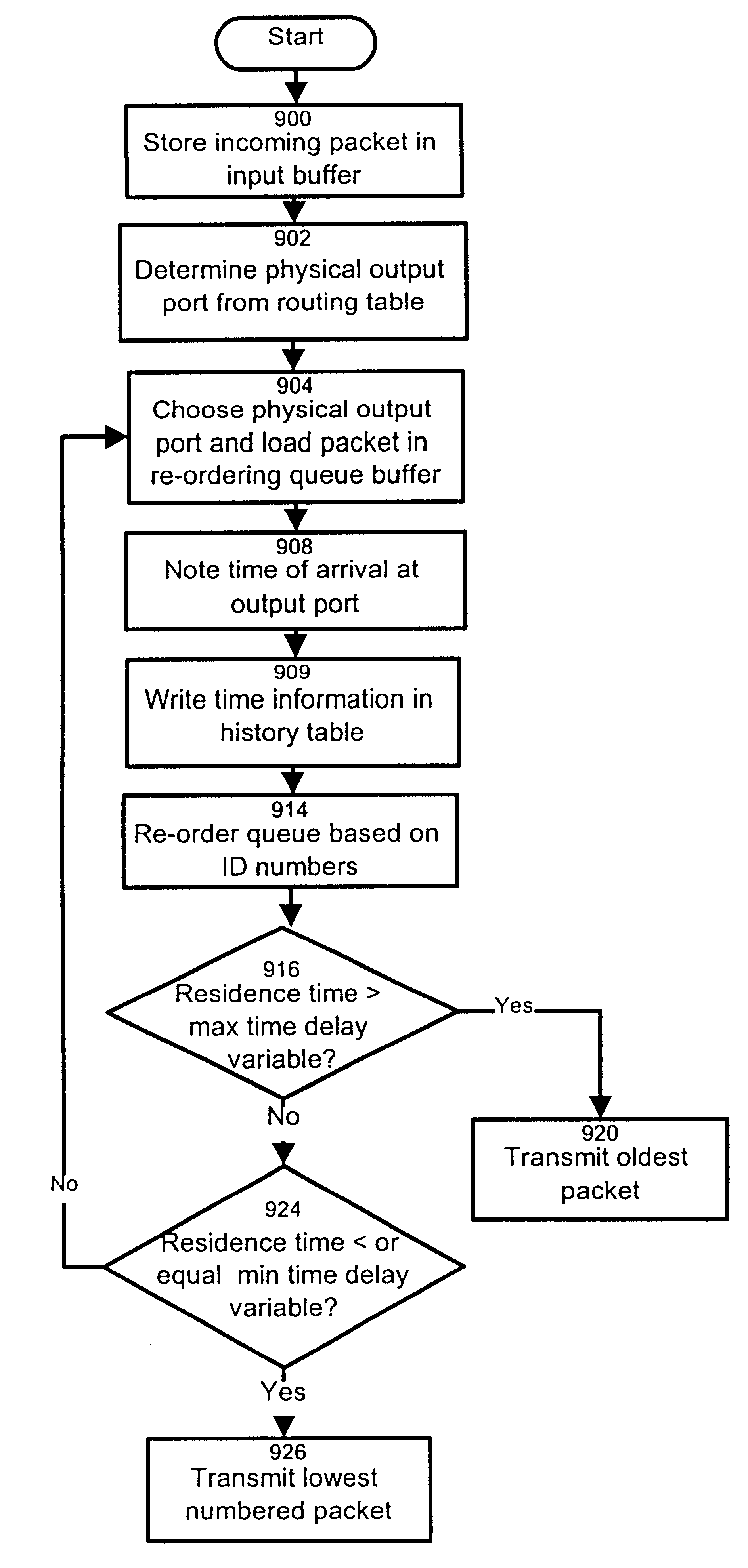
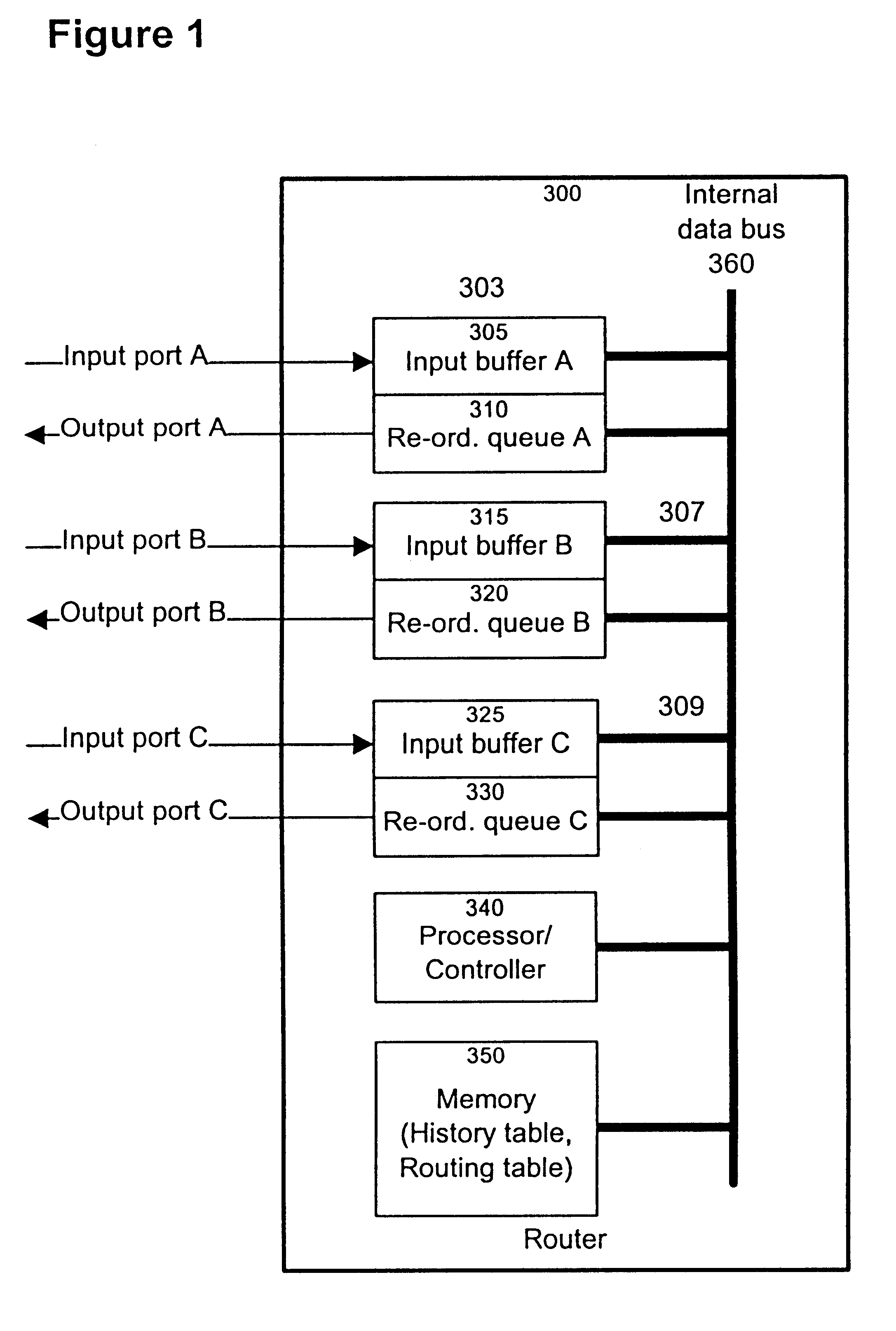
The structure of a router constructed in accordance with the present invention is shown in FIG. 1. The router 300 is comprised of interfaces 303, 307 and 309 that connect an internal data bus to the respective physical links A, B and C. In the example shown, each physical link supports two ports, namely an input port and an output port. Note that each physical input and output port may include a number of virtual input and output ports. The interfaces 303, 307 and 309 include input buffers 305, 315 and 325, and re-orderable queue storage media in the form of buffers 310, 320 and 330. The input buffers are memory spaces of the FIFO type that can hold input IP data packets received at the input port of the associated physical link. The purpose of the buffers is to provide a temporary storage mechanism allowing to hold the incoming IP data packets before a decision is made by the routing logic as to how those packets are to be handled. The physical configuration of the input buffers do...


PUM


Abstract

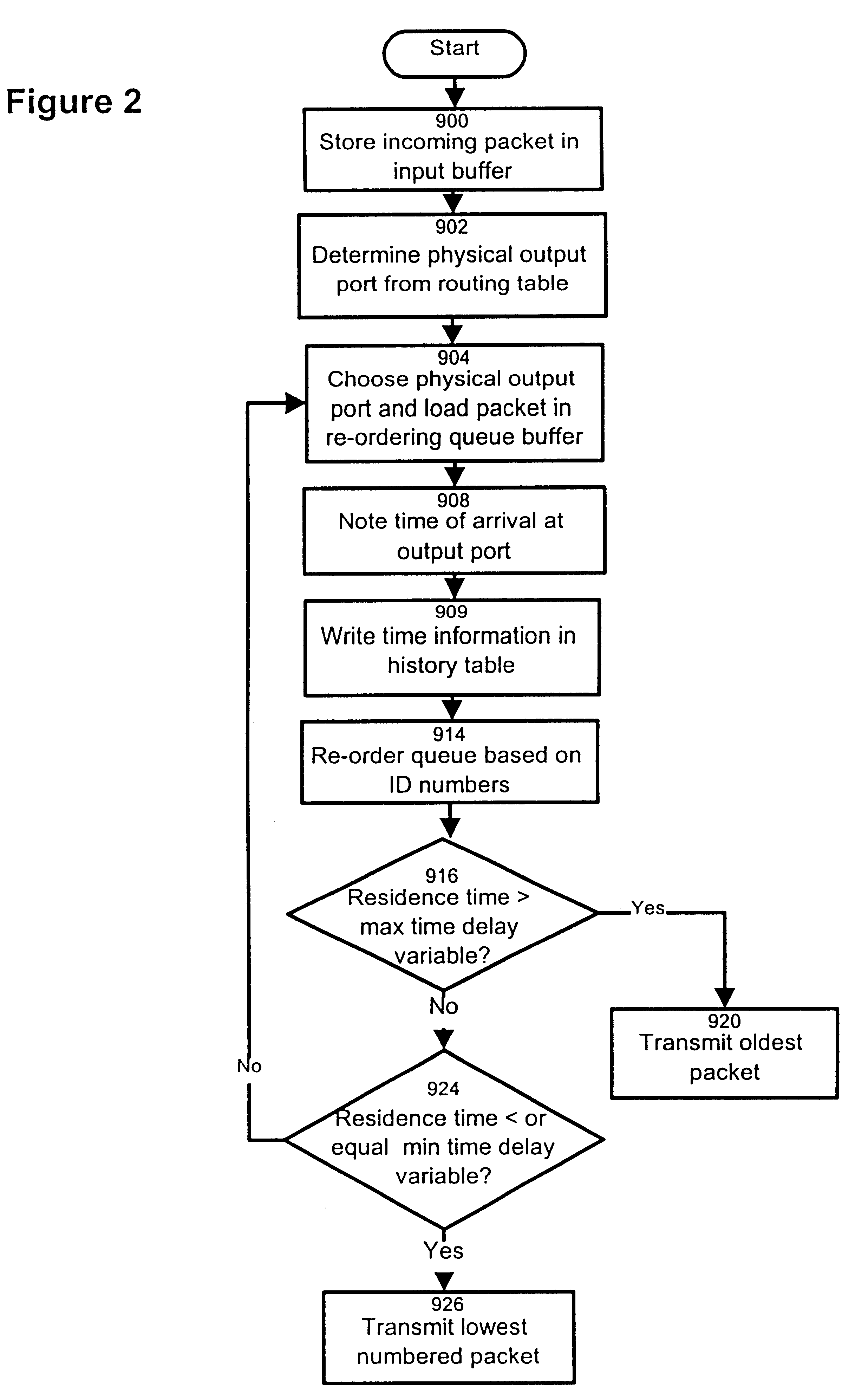
The invention provides a method and apparatus for re-ordering data traffic units, such as IP data packets, that may have been miss-ordered during a transmission over a multi-pathway link between a source node and a destination node in a network. The re-ordering apparatus includes a storage medium for intercepting the IP data packets and holding the IP data packets to allow IP data packets delayed on slower pathways to catch-up. The IP data packets in the storage medium are re-ordered based on their sequence number in an attempt to restore the original order of the IP data packets. A maximal time delay variable determines how long a certain IP data packet can be held in the storage medium. The TP data packet is released prior to the maximal time delay variable or as the maximal time delay variable is exceeded.

Description

The present invention relates to the field of data communications networks. More specifically, it pertains to devices and methods for re-ordering data traffic units at a destination node.The following paragraphs give definitions of terms used throughout this document.Physical Link: a single point-to-point (PPP) serial transmission link between two nodes in the network (such as between two routers or between a router and a host machine). The implementation of a serial link may take various forms such as an optical fiber a wavelength segment on an optical fiber among others.Physical output port: the output port of the router that supports one physical link.Logical link: A point-to-point traffic path between two routers that is composed of multiple parallel physical links and appears from a routing point of view to be one link.Logical output port: the collection of physical output ports that support the physical links of a logical link.Data traffic unit: a portion of the original traff...

Claims


Application Information

Patent Timeline
IPC IPC(8): H04L29/06H04L12/56
CPCH04L29/06H04L47/10H04L47/34H04L69/14H04L9/40
Inventor CHAPMAN, ALAN STANLEY JOHNKUNG, HSIANG-TSUNG
Owner RPX CLEARINGHOUSE
Learn More