
RFQ accelerator and ion implanter to guide beam through electrode-defined passage using radio frequency electric fields

a radio frequency electric field and accelerator technology, applied in the direction of machines/engines, mechanical equipment, vacuum evaporation coating, etc., can solve the problems of electrode oscillation and insufficient cooling ability

Inactive Publication Date: 2001-05-29
NISSIN ION EQUIP CO LTD
View PDF7 Cites 13 Cited by
  • Summary
  • Abstract
  • Description
  • Claims
  • Application Information

AI Technical Summary

Benefits of technology

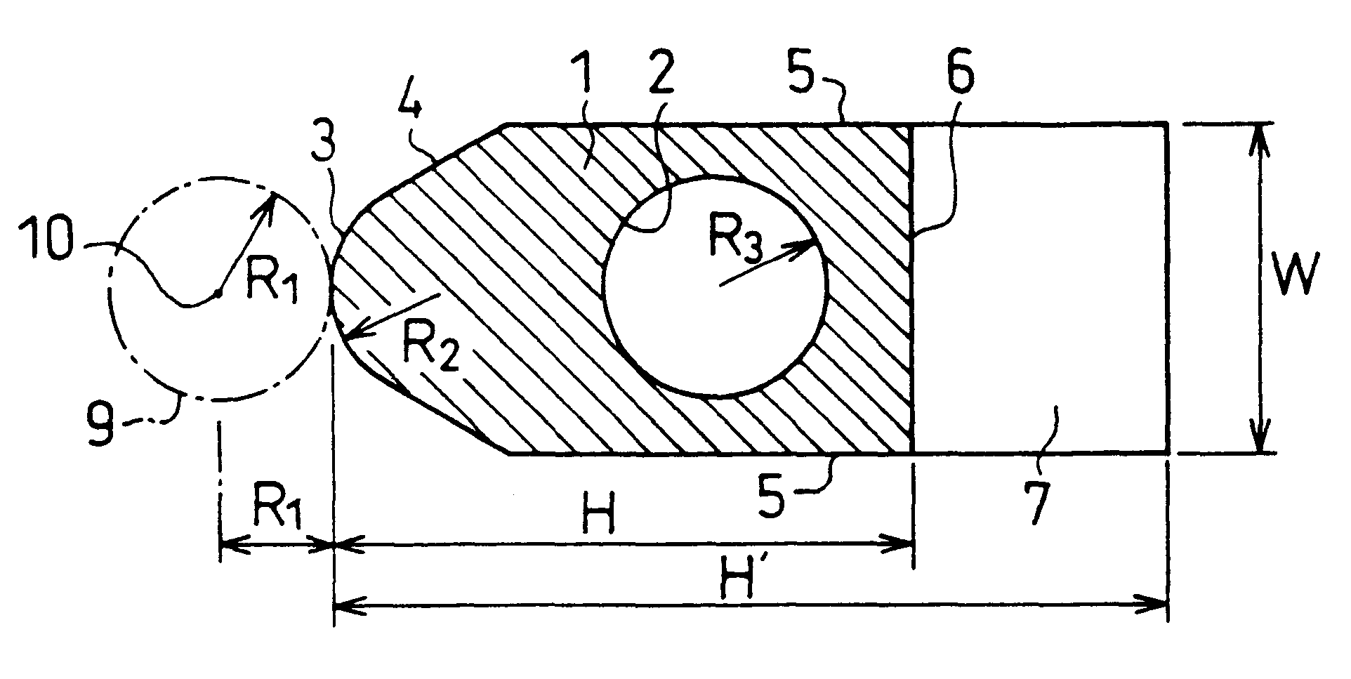
In general, in an RFQ accelerator, when the electrode height H is reduced, shunt impedance increases and the power efficiency is improved. Yet, because the cross section of the coolant channel cannot be increased, problems are likely to occur that cooling ability becomes insufficient, and the mechanical strength suffers, causing the electrodes to oscillate. However, with the described arrangement, it is possible to realize an optimum configuration of the RFQ electrodes in which, with respect to a low resonance frequency of 25 MHz to 50 MHz suitable for heavy ions such as B, P, and As, power efficiency is high, cooling ability is superior, mechanical strength is sufficient, and beam acceptance is large.
With this arrangement, because the electrodes are fixed to the posts by bolts through screw holes with a direct contact, it is possible to improve electric and thermal conductance.
With this arrangement, because the entire electrode surface meeting the beam passage spacing is composed of a combination of circular arc and line, instead of circular arc alone, it is possible to machine the electrodes with ease.
With this arrangement, compared with the case where the coolant channel is provided by blazing a copper pipe to a vane electrode, it is possible to reduce distortion on the electrode due to the heat generated in the machining process and improve the cooling efficiency.
With this arrangement, because the posts partially constituting an RFQ resonance circuit are disposed at equal intervals on one side of an acceleration tube, it is possible to minimize the resonance frequency of the RFQ while maintaining simple assemblage.
With this arrangement, it is possible to realize a high energy ion implanter in the order of several MeV and a large current high energy ion irradiating device in a size and cost that are compact and low enough to be applied in an industrial setting such as in semiconductor industry.

Problems solved by technology

Yet, because the cross section of the coolant channel cannot be increased, problems are likely to occur that cooling ability becomes insufficient, and the mechanical strength suffers, causing the electrodes to oscillate.

Method used


Image

  • RFQ accelerator and ion implanter to guide beam through electrode-defined passage using radio frequency electric fields
  • RFQ accelerator and ion implanter to guide beam through electrode-defined passage using radio frequency electric fields
  • RFQ accelerator and ion implanter to guide beam through electrode-defined passage using radio frequency electric fields

Examples


Embodiment Construction

In order to achieve the above-mentioned object, the present invention finds and optimizes parameters for improving the power efficiency of RFQ electrodes using three-dimensional dynamic electromagnetic field analysis code, taking into consideration cooling ability, mechanical strength, and assemblage simplicity, etc.

FIG. 4 shows a projection of an RFQ accelerator employing RFQ electrodes of the present invention. A large circle indicates the size of a vacuum chamber. Inside the vacuum chamber are installed the RFQ electrodes, posts, and a base. The shadow on the center resembling four petals of a flower is a projection of the RFQ electrodes. A rectangular plate with an inclined surface is a projection of one of two kinds of the posts. It is clearly depicted how a pair of electrodes on a diagonal line are connected to the post.

In FIG. 4, a space is divided into a vertical and horizontal array of lattices at regular intervals, and the strength of magnetic field is shown at each lattic...


PUM

PropertyMeasurementUnit
heightaaaaaaaaaa
bore radius R1aaaaaaaaaa
diameteraaaaaaaaaa

Abstract

RFQ electrodes for use as an acceleration tube of a high energy ion implanter, capable of accelerating an ion beam of large current without divergence are arranged, with respect to a low resonance frequency of substantially 33 MHz suitable for heavy ions such as B, P, and As, such that a radius R1 of a beam passage spacing surrounded by four RFQ electrodes is 5 mm to 9 mm, a curvature R2 in a direction perpendicular to an axis of a crest portion of repetitive crest and trough portions on surfaces of the electrodes in a beam propagation direction is 5 mm to 9 mm, and a height H from a peak of the crest portion to a bottom surface is set so that H / R1 is 4 to 6. When the height H of the electrodes is reduced, while shunt impedance is increased and power efficiency is improved, a cooling ability becomes insufficient due to the fact that a cross section of a coolant channel cannot be increased, and a problem is presented that oscillation of electrodes is likely to occur due to insufficient mechanical strength. However, by adopting the above arrangement, an optimum configuration of the RFQ electrodes is obtained, in which power efficiency is high, cooling efficiency is superior, a mechanical strength is sufficient, and beam acceptance is large.

Description

The present invention relates to an RFQ accelerator and an ion implanter provided with thereof for use in ion irradiation and ion implantation, and particularly relates to an improvement in electrode configuration of such an RFQ accelerator.An RFQ accelerator is capable of accelerating an ion beam with a focusing force and thus capable of accelerating an ion beam of large current without divergence, and therefore is used as a high energy ion acceleration tube of a high energy ion implanter. The RFQ accelerator also has its application as an ion accelerator of experimental, analytical, and medical use.As representative accelerators of charged particles, circular accelerator and linear accelerator are available. The circular accelerator, such as cyclotron, accelerates a beam in a circular motion and the linear accelerator accelerates a beam in a linear motion. The RFQ accelerator is an example of the latter. The linear accelerator works under the principle that ions are accelerated by...

Claims


Application Information

Patent Timeline
Patent Type & Authority Patents(United States)
IPC IPC(8): H05H7/04H05H9/00H05H7/00H05H9/04C23C14/48H01J37/317H01L21/265
CPCH05H7/00H05H7/04H05H9/00H05H9/04
Inventor FUJISAWA, HIROSHI
Owner NISSIN ION EQUIP CO LTD
Learn More