
High aspect ratio, microstructure-covered, macroscopic surfaces

Inactive Publication Date: 2001-03-06
BOARD OF SUPERVISORS OF LOUISIANA STATE UNIV & AGRI & MECHANICAL COLLEGE
View PDF22 Cites 84 Cited by
  • Summary
  • Abstract
  • Description
  • Claims
  • Application Information

AI Technical Summary

Benefits of technology

The performance of many macroscopic structures (those whose dimensions are on the order of centimeters, meters, or even larger) can be greatly improved by covering their surfaces with microstructures.
It has been discovered that the performance of many macroscopic structures (those whose dimensions are on the order of centimeters, meters, or even larger) can be greatly improved by covering their surfaces with microstructures. In addition, a novel apparatus and method have been discovered for forming high aspect ratio microstructures ("HARMs") on planar and non-planar surfaces, using a modification of the LIGA microfabrication process. A free-standing, non-conductive sheet (e.g., a polymer or ceramic sheet) is patterned lithographically or by LIGA with through-holes. The non-conductive sheet is then pressed against, clamped to, or otherwise attached to a conductive substrate in such a way that the patterned holes in the sheet are not blocked. Subsequent electroplating produces well-defined HARM structures on the planar or non-planar surface, in shapes that are complementary to the lithographically patterned through-holes in the non-conductive sheet. The sheet may then be removed (e.g., by melting, dissolution, or burning).

Problems solved by technology

Using conventional methods, it is difficult if not impossible to make a heat shield that simultaneously satisfies each of these design considerations.

Method used


Image

  • High aspect ratio, microstructure-covered, macroscopic surfaces
  • High aspect ratio, microstructure-covered, macroscopic surfaces
  • High aspect ratio, microstructure-covered, macroscopic surfaces

Examples


example 2

HARMs Fabricated on a Cylindrical Shaft

The novel process has been used to fabricate HARMs on a nickel cylinder of diameter 1.0 cm. A square-grid mask was used to lithographically pattern a free-standing sheet of PMMA of thickness 300 .mu.m using the CAMD synchrotron x-ray radiation source. The nickel cylinder was placed vertically on a hot plate and brought to a temperature of approximately 100.degree. C. The exposed PMMA sheet was held above the same hot plate until it became flexible, at which point it was wrapped around the cylinder and secured with a clamp. The cylinder was removed from the hot plate and cooled to room temperature. Because the thermal expansion coefficient of PMMA is greater than that of nickel, the PMMA shrink-fit onto the nickel cylinder.

The PMMA was then developed by immersing the PMMA-coated nickel cylinder into GG developer (V. Ghica and W. Glashauser, "Verfahren fur die Spannansfreie Entwicklung von Bestrahlten Polymethyl-methacrylat-Schichtyen," Offenlegu...

example 3

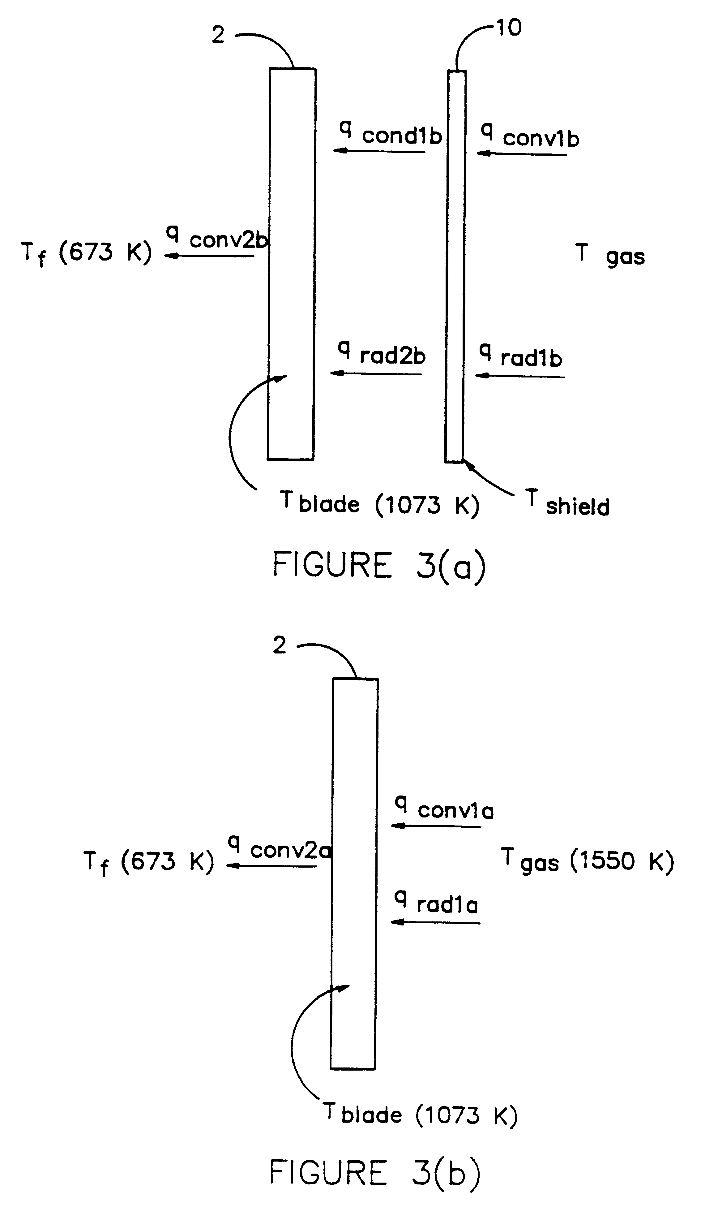
Thermal banners; application to turbine blades

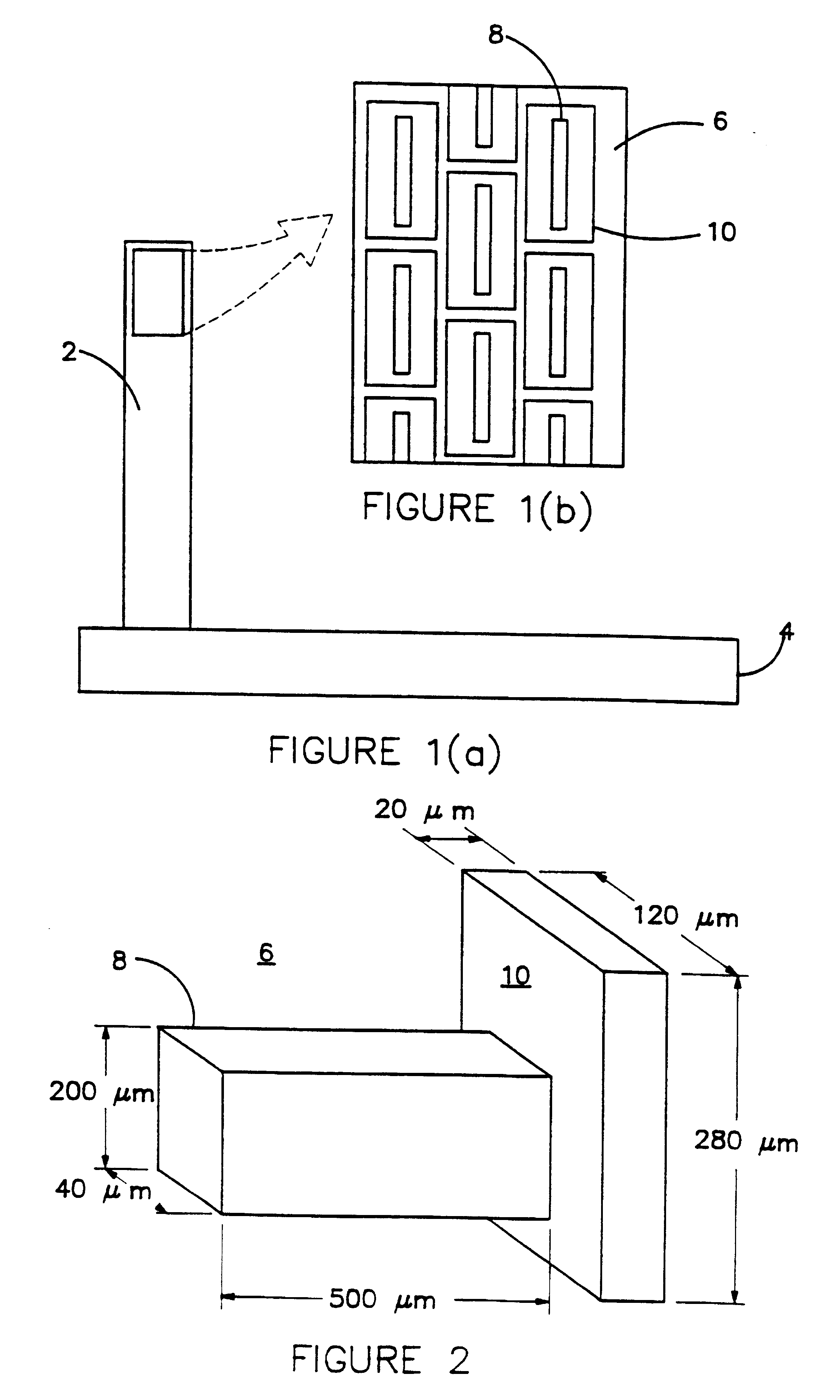
In one embodiment, thermal barrier microstructures will be manufactured on a turbine blade. A mold insert will be manufactured to mold or emboss a pattern of microstructures into a thin film of polymer as described above. The polymer film, containing voids where structures in the mold insert were present, is applied to the blade surface. An electroplating process then fills voids in the polymer with metal, thereby building a field of microstructures on the blade surface. By overplating beyond the height of the polymer, caps can be grown on top of the posts if desired; if the caps are allowed to grow large enough, they can form a continuous wall connected to the substrate by numerous microposts. Following the electroplating process, the polymer film is removed, for example with a solvent, leaving a metallic microstructure canopy on the surface.

It is preferred that there be a smooth transition from a material at the base of the microstruct...

example 4

Prototype Manufactures

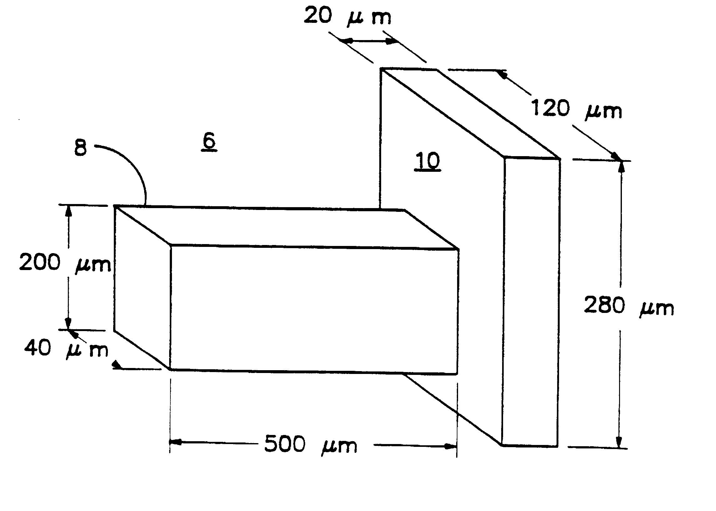
In one prototype, "mushroom" shaped canopies were manufactured 300 .mu.m tall, with 170.times.170 .mu.m square posts, topped by square canopies 300 to 300 .mu.m in diameter at the base.

A 0.1 .mu.m-thick nickel film, deposited from a modified Watts bath, adhered well to a silicon wafer. The composition of the modified Watts bath was as follows: NiSO.sub.4. 6H.sub.2 O (300 grams / liter), NiCl.sub.2.6H.sub.2 O (45 grams / liter), boric acid (45 grams / liter), sodium lauryl sulfate (0.3-0.5 grams / liter), saccharin (0.5-1.0 grams / liter), coumarin (0.5 grams / liter), pH 2.0, temperature 55.degree. C. The sodium lauryl sulfate acted as a surfactant, and the saccharin acted as a stress reliever to help produce fine grains. The anode was a nickel foil. High current densities of 0.1 to 0.2 A / cm.sup.2, corresponding to a nickel deposition rate of 100-150 .mu.m / hour, lowered the time required to electroplate the 490 .mu.m tall nickel prototype structures to just four hours. Pro...


PUM

PropertyMeasurementUnit
Flexibilityaaaaaaaaaa
Electrical conductoraaaaaaaaaa
Microstructureaaaaaaaaaa

Abstract

The performance of many macroscopic structures (those whose dimensions are on the order of centimeters, meters, or even larger) can be greatly improved by covering their surfaces with microstructures. There are several applications in which "large," microstructure-covered sheets are useful. An apparatus and method are disclosed for forming high aspect ratio microstructures ("HARMs") on planar and non-planar surfaces, using a modification of the LIGA microfabrication process. A free-standing polymer sheet is lithographically patterned with through-holes. The polymer sheet is then pressed against, clamped to, or otherwise attached to a conductive substrate in such a way that the patterned holes in the sheet are not blocked. Subsequent electroplating produces well-defined HARM structures on the planar or non-planar surface, in shapes that are complementary to the lithographically patterned through-holes in the polymer. The polymer may then be removed (e.g., by melting, dissolution, or burning). Various planar and non-planar surfaces have been covered with microstructures. Where the metal surface is non-planar, the polymer sheet may be heated or otherwise made sufficiently flexible to conform to the metal surface, preferably by heat-shrinking to assure firm contact. The process may be used to electroplate microstructures directly onto metal surfaces generally-not just onto metal surfaces that have been specially prepared for LIGA processes, as has previously been the case.

Description

This invention pertains to macroscopic surfaces whose properties are altered by being covered with microstructures, and to an apparatus and method useful in manufacturing such surfaces.The properties of many macroscopic structures depend in large part on their surface properties. For example, the rate of heat transfer between a structure and its surroundings depends on the ease with which radiative, conductive, and convective heat transfer occur between the surface of the structure and the surroundings. As another example, the strength of composite materials is often governed by the strength of the bond between the "internal" surfaces joining the different lamina. As yet another example, the rate of activity of a catalytic surface often depends on its surface area.Efforts have been made to control the interaction of surfaces with their surroundings by painting, roughening, anodizing, hardening, plating, smoothing, and the like. In many cases, the resulting improvements in surface pr...

Claims


Application Information

Patent Timeline
IPC IPC(8): B01J19/00B81C1/00C25D5/02F28F13/18F28F13/00
CPCB01J19/0093B81C1/00619B81C99/0085C25D5/022F28F13/185B01J2219/00783B01J2219/00822B01J2219/00828B01J2219/00833B01J2219/00873B01J2219/00995F28F2260/02
Inventor KELLY, KEVIN W.
Owner BOARD OF SUPERVISORS OF LOUISIANA STATE UNIV & AGRI & MECHANICAL COLLEGE
Learn More