
Method for a controlled bottle trench for a dram storage node

a bottle trench and storage node technology, applied in the field of dram storage nodes, can solve the problems of critical dimensional control of bottle etching, no specific doping process step tailored to control the etching rate, and enlarged capacitor surface area

Inactive Publication Date: 2001-02-20
IBM CORP
View PDF14 Cites 63 Cited by
  • Summary
  • Abstract
  • Description
  • Claims
  • Application Information

AI Technical Summary

Problems solved by technology

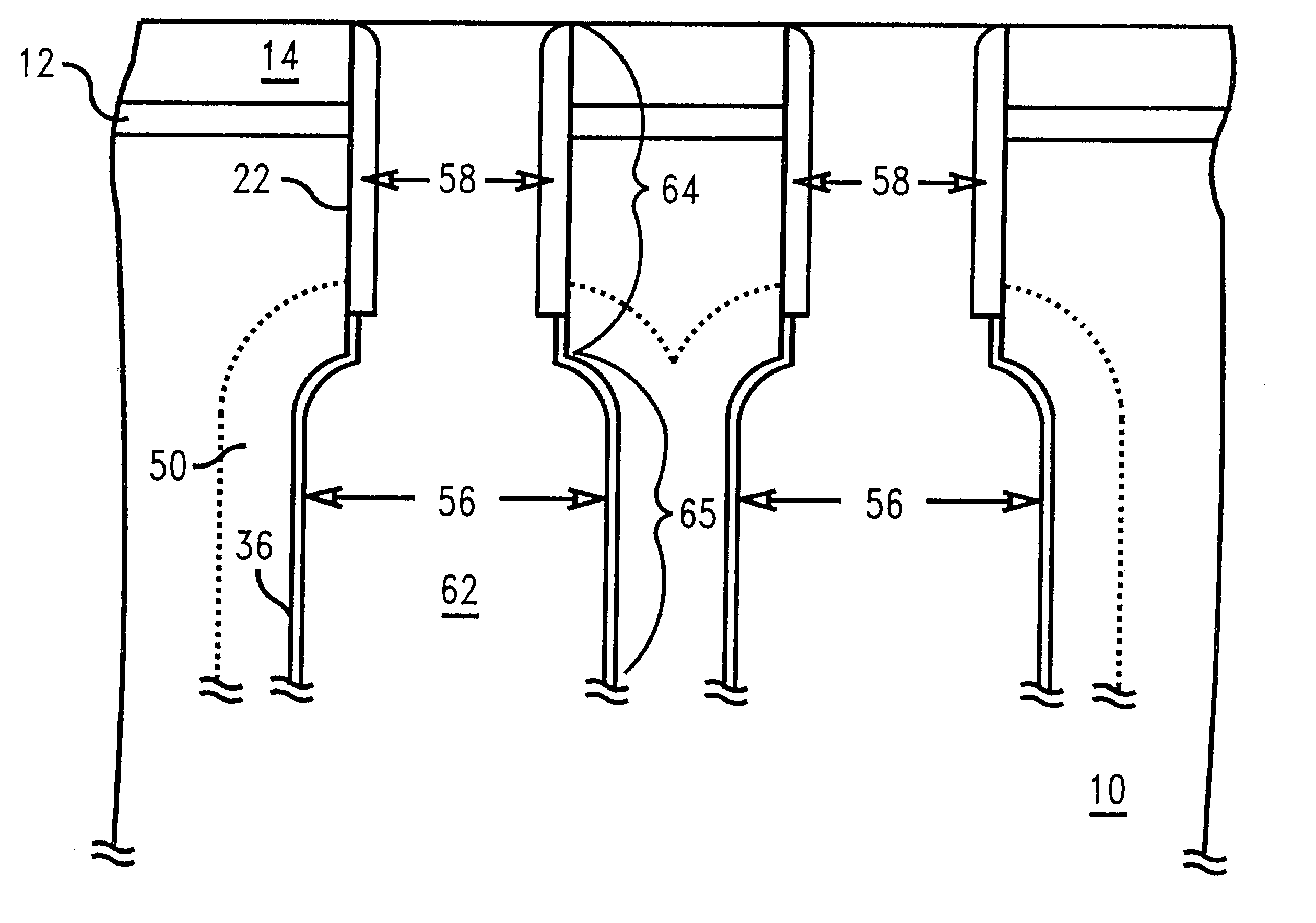
However, as only the bottom region of the trench is etched, the capacitor surface area, although enlarged, is not maximized.
There is no doping process step specifically tailored to control the etch rate.
Thus, the dimensional control of bottle etching becomes critical.
The existing prior art for creating bottle shaped trenches by dry etching lacks precise control as a result of not having an associated etch stop.

Method used


Image

  • Method for a controlled bottle trench for a dram storage node
  • Method for a controlled bottle trench for a dram storage node
  • Method for a controlled bottle trench for a dram storage node

Examples


Embodiment Construction

)

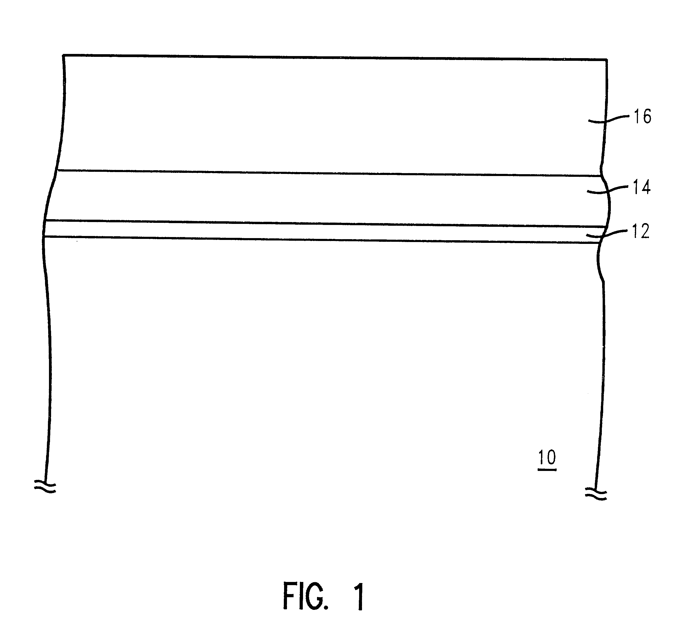
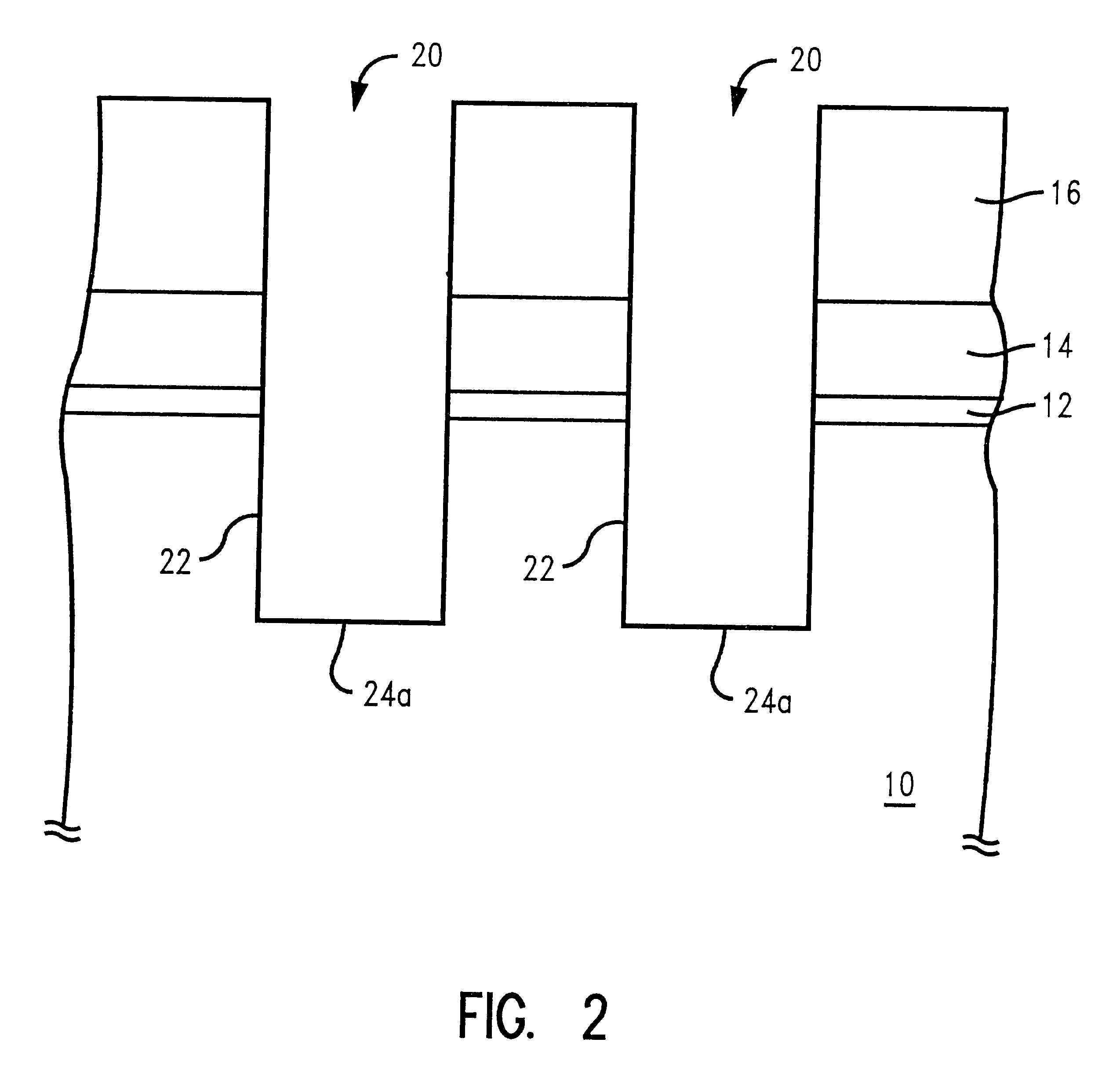
In describing the preferred embodiment of the present invention, reference will be made herein to FIGS. 1-8 of the drawings in which like numerals refer to like features of the invention. Features of the invention are not necessarily shown to scale in the drawings.

In the prior art, trench to trench dimensions are already close to or at a minimum as defined by current lithographic techniques. In order to increase the capacitance, the extra surface area created by widening the trench region may cause adjacent trenches to be closer than the minimum required separation distance. Or, in the worst case, adjacent trenches may merge together. Thus, the control of trench etching becomes critical. The capacitance may be increased by deepening the trench, but the resistance increases to degrade the performance. Also, the deep trench etch process may become too long to be practical. In the present invention, the precise trench dimension control is achieved by doping a silicon substrate around ...


PUM


Abstract

A bottle-shaped trench capacitor with a buried plate is formed in a controlled etch process. The bottle-shape is fabricated by etching deep trenches from a layered substrate, using the layers as a mask, and covering the side walls of the substrate with protective oxide and nitride layers. With the side walls covered, deep trench etching is then resumed, and a lower trench portion, below the protective layers of the side wall are formed. By diffusing a first dopant in the lower portion of the deep trench region, using the side wall protective layers as a mask, an etch stop is established for a wet etch process at the p / n junction established by the first dopant. The width of the lower trench portion is regulated by the time and temperature of the diffusion. Removing the doped material and applying a second dopant to the lower trench portion establishes a continuous buried plate region between trenches. A capacitor is formed by applying an insulating layer to the trench and filling with a conductor.

Description

1. Field of the InventionThe present invention relates to a semiconductor device, and more particularly to a trench capacitor cell. Specifically, the invention involves the controlled formation of bottle trench capacitors.2. Description of Related ArtAs the integration density of a Dynamic Random Access Memory (DRAM) steadily increases, it becomes necessary to reduce the memory cell size. The memory cell size is primarily determined by the minimum resolution dimension of a lithographic technique, the overlay tolerances between the different features and the layout of these features. At the same time, it is necessary to maintain the minimum required storage capacitance to reliably operate the DRAM. To meet both the cell size requirement and the storage capacitance requirement, a trench capacitor was invented; the simple single device / capacitor memory cell has been altered to provide the capacitor in a vertical dimension. In such designs, the capacitor is formed in a trench in the sur...

Claims


Application Information

Patent Timeline
Patent Type & Authority Patents(United States)
IPC IPC(8): H01L21/70H01L21/8242H10B12/00
CPCH01L27/1087H10B12/0387
Inventor FURUKAWA, TOSHIHARUHAKEY, MARK C.HOLMES, STEVEN J.HORAK, DAVIDMA, WILLIAM H.NEVER, JAMES M.
Owner IBM CORP
Learn More