Coated hard metal material

Inactive Publication Date: 2001-02-06
SUMITOMO ELECTRIC IND LTD
View PDF24 Cites 72 Cited by
  • Summary
  • Abstract
  • Description
  • Claims
  • Application Information

AI Technical Summary

Benefits of technology

Another object of the present invention is to provide a coated hard metal material for a cutting tool which can sufficiently withstand usage not only in an ordinary cutting condition but under such a severe cutting condition of a high speed or high efficiency that the cutting edge temperature exceeds 1000.degree. C.
In the present invention, the outer layer is made thicker than the inner layer, and the thickness of the outer layer is especially set to be at least 5 .mu.m. Thus, the present invention can maintain good wear resistance for a longer time in cutting conditions from a low speed up to a high speed. Further, the present invention employs Al.sub.2 O.sub.3 or ZrO.sub.2 which is excellent in heat insulation for the intermediate layer. Particularly the intermediate layer suppresses propagation of heat which is generated in the cutting edge to the base material during cutting work, and suppresses plastic deformation of the base material caused by heat. When deformation of the base material in cutting work is suppressed, separation of the coating is also suppressed. In the present invention, the intermediate layer which is mainly composed of Al.sub.2 O.sub.3 is at least 5 .mu.m thick, and the intermediate layer which is mainly composed of ZrO.sub.2 is at least 0.5 .mu.m thick, as the thickness of the intermediate layer providing sufficient heat insulation. In the present invention, the inner layer particularly contributes to adhesion of the hard coating layers. onto the base material. On the other hand, the intermediate layer and the outer layer particularly contribute to heat insulation and wear resistance respectively. Thus, the present invention makes the three layers provide or carry out different functions respectively, for obtaining a coated hard metal material which can exhibit excellent performance in wide-ranging cutting conditions. Further, a superior result can be obtained by setting the thicknesses of the respective layers in proper ranges and / or improving adhesion between the respective layers, as described later.

Problems solved by technology

However, the cutting edge temperature of the cutting tool exceeds 1000.degree. C. in such a cutting condition, and this is an extremely severe condition for the tool material.
If the cutting edge temperature is increased, the cutting edge is plastically deformed by heat, to cause regression of the cutting edge position.
At a temperature exceeding 1000.degree. C., further, the base material such as cemented carbide forming the tool is oxidized and wear abruptly progresses.
It has been recognized that, if such a tool is used in practice, the dimensions of the workpiece being cut are changed by regression of the cutting edge position since the progress of wear is quick, and the life of the tool is extremely short.
In using such a tool for cutting with a large impact such as intermittent cutting, it has generally occurred that damage is abruptly increased due to layer separation in the flank and the cutting face, which abruptly reaches the end of or terminates the tool life.
However, the function of the outer layer as an adiabatic layer is reduced by wear in an early stage, while no specific advice or consideration is given as to wear resistance of the outer layer either.
Thus, progress of wear is quick, and the life of the tool was extremely short.
However, no tool employing ZrO.sub.2 as a coating layer has been put into practice up to now.
This is because a ZrO.sub.2 layer is inferior in wear resistance since the hardness of ZrO.sub.2 is low as compared with Al.sub.2 O.sub.3.
However, when a cutting tip made of such a conventional coated hard metal material is employed in high-speed cutting, particularly in such cutting conditions in which the cutting edge temperature exceeds 800.degree. C., there have been such problems that the cutting edge of the tip is easily damaged, and dimensional change of the workpiece easily takes place.

Method used


Image

  • Coated hard metal material
  • Coated hard metal material
  • Coated hard metal material

Examples


example 1

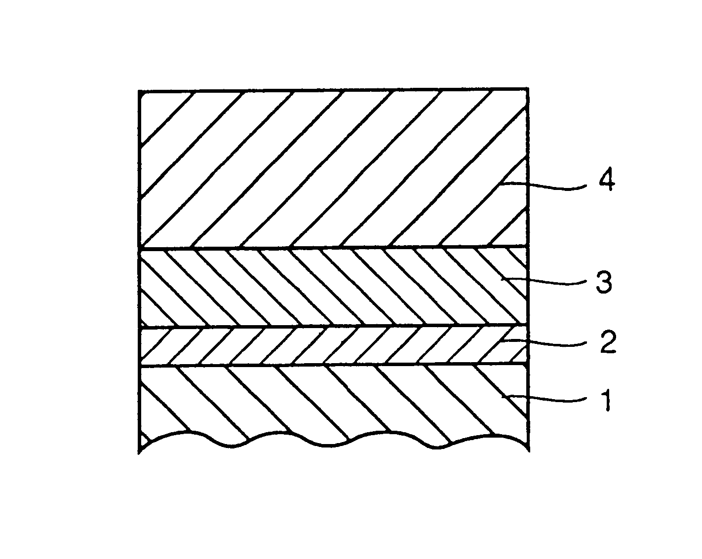
ISO M20 cemented carbide (base material 1), ISO K20 (base material 2) and a commercially available cermet tool material (base material 3) were prepared as base materials, and each one of hard coating layers shown in Table 1 was formed on each base material by well-known chemical vapor deposition at a deposition temperature of 1000.degree. C., to prepare tip-shaped tools according to SNGN120408 respectively.

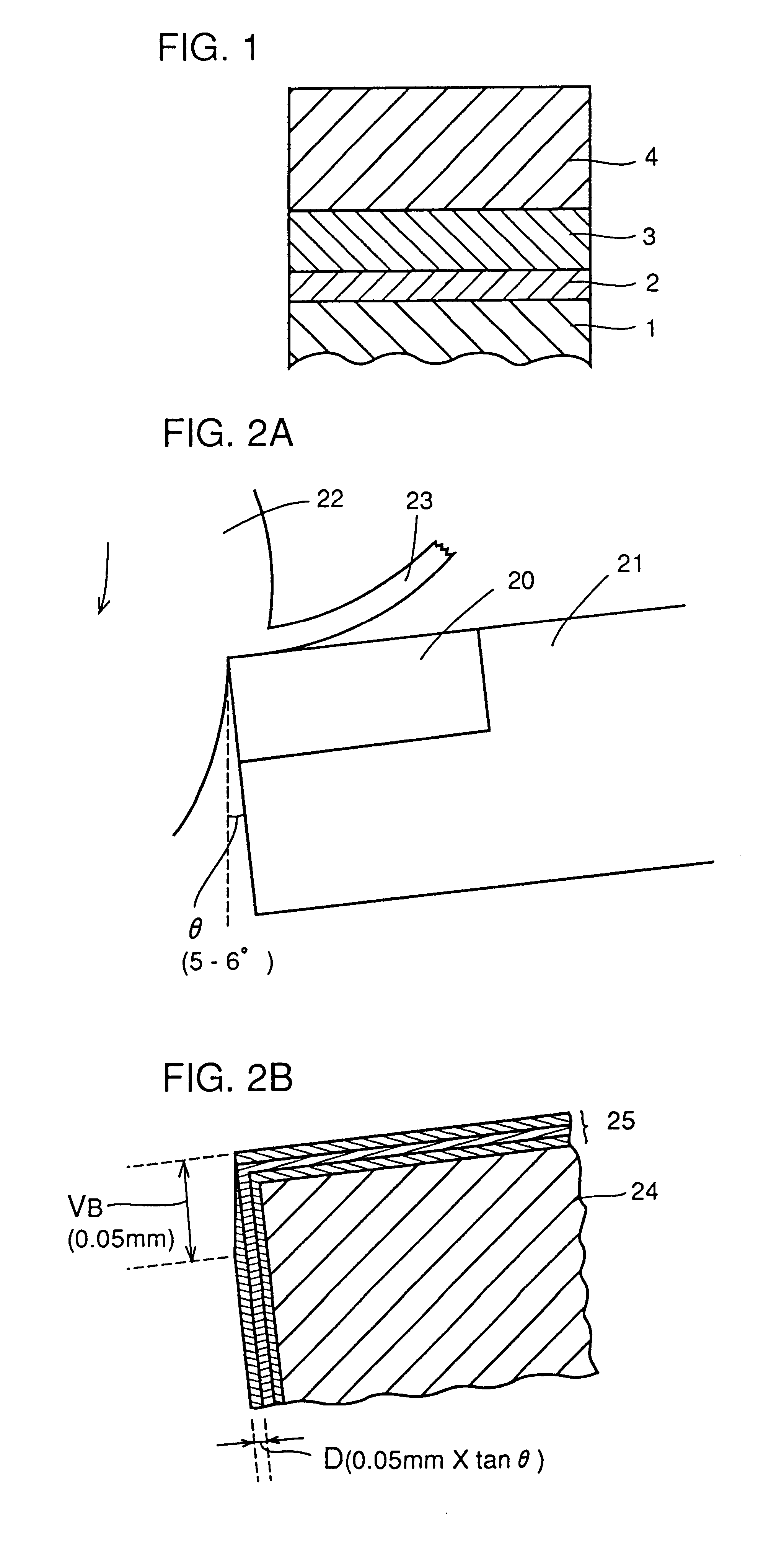
The respective tips having the hard coating layers formed on the base materials were employed for cutting workpieces of SCM415 under cutting conditions shown in the following Table 2, and cutting performance was evaluated. The results are shown in Table 3, along with the combinations of the base materials and the hard coating layers.

TABLE 3

From the above results, it is understood that the tips of the samples 1 to 4 of inventive Example exhibit excellent cutting performance not only in high-speed cutting (cutting condition 1) but also in low-speed cutting (cutting condition 2). By ...

example 2

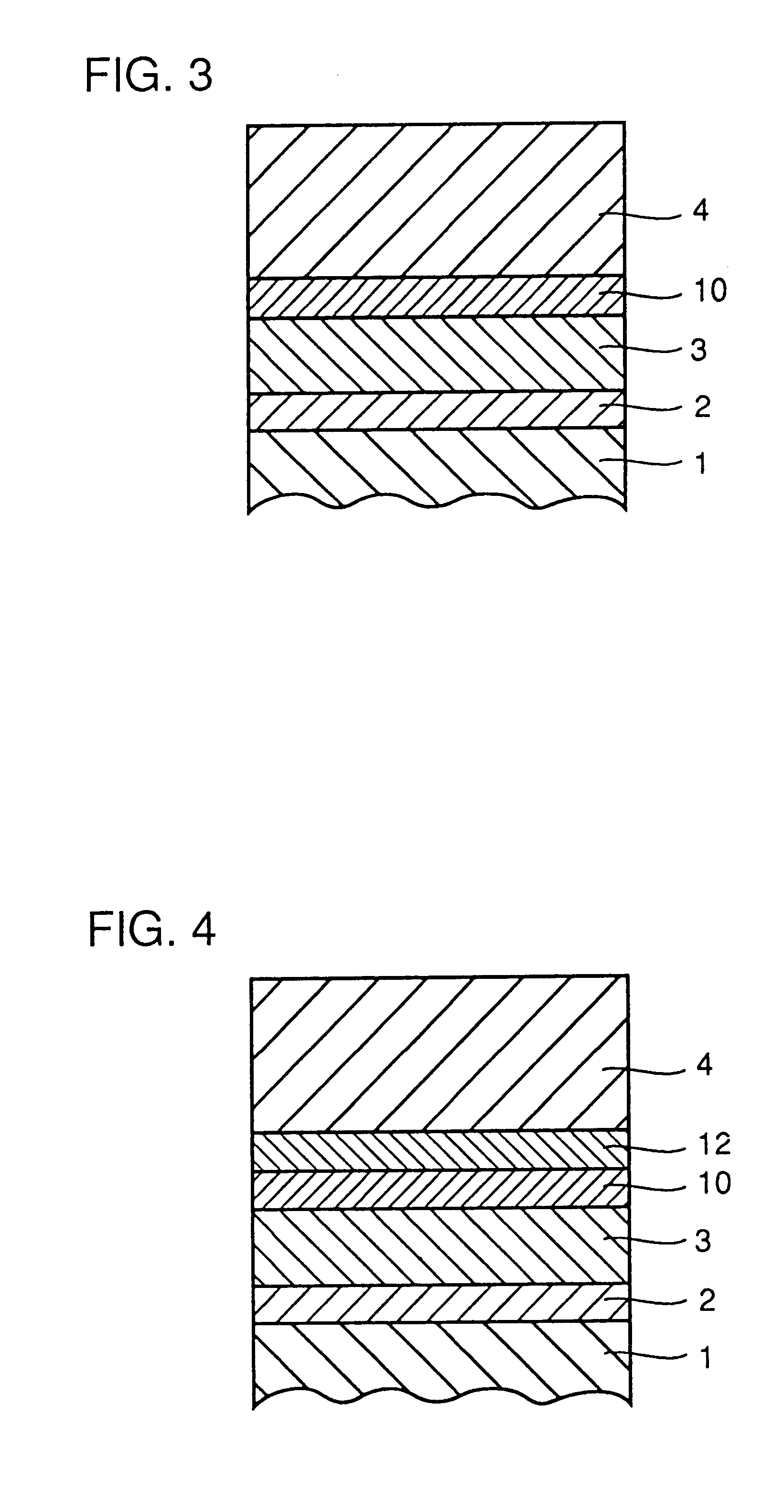
Hard coating layers shown in the following Table 4 were formed on surfaces of the base materials 1 in the above Example 1, to prepare tips of samples 9 to 14. These tips were employed for evaluating cutting performance under the cutting condition 2 similarly to Example 1. A workpiece 7 consisting of SCM435 having four grooves 8 on its circumference as shown in FIG. 9 was employed for testing chipping resistance under the cutting condition 3 of the above Table 2. The chipping resistance was evaluated by cutting times up to chipping of the tips. These results are shown together in Table 4.

As understood from the above results, the sample 9 having no Ti compound as an inner layer suffered separation of the coating layers in an early stage in a wear resistance test since adhesion of the coating layers was low, and had an extremely short life. The tip of the sample 14 exhibited a slightly inferior chipping resistance since the film thickness of the inner layer was large, while the same is...

example 3

Hard coating layers shown in the following Table 5 were formed on surfaces of the base materials 2 in the above Example 1, to prepare tips of samples 15 to 21. These tips were employed for evaluating cutting performance by the cutting condition 1 similarly to Example 1. Similarly to Example 2, further, chipping resistance was tested by the cutting condition 3. These results are shown together in Table 5.

As Understood from the above results, the samples other than the sample 15 having a small film thickness of the intermediate layer of Al.sub.2 O.sub.3 and the sample 21 having a large thickness exhibited cutting performance which is excellent in balance between wear resistance and chipping resistance, and the tips of the samples 17, 18 and 19 exhibited particularly excellent cutting performance above all.


PUM

PropertyMeasurementUnit
Volumeaaaaaaaaaa
Fractionaaaaaaaaaa
Fractionaaaaaaaaaa

Abstract

A coated hard metal for a cutting tool is excellent in wear resistance and chipping resistance. The coated hard metal includes a hard coating layer on a surface of a base material of cemented carbide or cermet. The hard coating layer includes an inner layer (2) on the base material (1), an intermediate layer (3) on the inner layer (2) and an outer layer (4) on the intermediate layer (3). The inner layer (2) consists of a carbide, a nitride, a carbo-nitride, a carbo-oxide, a carbonitrogen oxide or a boronitride of Ti. The intermediate layer (3) consists of Al2O3 or ZrO2. The outer layer (4) consists of a carbide, a nitride, a carbo-nitride, a carbo-oxide, a carbonitrogen oxide or a boronitride of Ti. The thickness of the inner layer (2) is 0.1 to 5 mum, the thickness of the intermediate layer (3) is 5 to 50 mum in the case of it being an Al2O3 layer and 0.5 to 20 mum in the case of it being a ZrO2 layer, and the thickness of the outer layer (4) is 5 to 100 mum.

Description

The present invention relates to a coated hard metal material prepared by coating cemented carbide or cermet with a hard material, and more particularly, it relates to a coated hard metal material which is employed for a cutting tool. The present invention provides a cutting tool material which is excellent in wear resistance and chipping resistance, and can withstand a high-speed or high-efficiency cutting condition, in particular.BACKGROUND INFORMATIONIt is known that a cutting edge temperature of a cutting tool during cutting exceeds about 800.degree. C. at the maximum even under an ordinary cutting condition with a cutting rate of about 100 to 300 m / min. Further, in recent years, manufacturers who use machining operations, such as especially a car manufacturer, have increased the demand for development of a tool which can be used for cutting under a condition of a higher speed or a higher feed rate than the conventional one, such as a high speed of at least 300 m / min., for examp...

Claims


Application Information

Patent Timeline
IPC IPC(8): C23C28/04C23C30/00
CPCC23C28/04C23C28/044C23C30/005Y10T428/265Y10T428/12743Y10T428/12785Y10T428/24975Y10T428/12771Y10T428/26Y10T407/27
Inventor MORIGUCHI, HIDEKIIKEGAYA, AKIHIKOKITAGAWA, NOBUYUKIUCHINO, KATSUYA
Owner SUMITOMO ELECTRIC IND LTD
Why Eureka
Try Eureka