Amplifier with feedforward loops for rejecting non-linear distortion

a non-linear distortion and amplifier technology, applied in amplifiers, amplifiers with semiconductor devices/discharge tubes, frequency-division multiplexes, etc., can solve problems such as the inability or the inability to eliminate, and the distortion of carrier imd at a frequency identical to or extremely close to that of a carrier like imd (intermodulation distortion) is likely to occur, and the inability to compensate for such distortions

Inactive Publication Date: 2001-01-09
JAPAN RADIO CO LTD
View PDF12 Cites 40 Cited by
  • Summary
  • Abstract
  • Description
  • Claims
  • Application Information

AI Technical Summary

Problems solved by technology

A variety of distortions exist that are caused by the non-linearity of the amplifier.
Among those distortions, distortion being produced at a frequency identical to or extremely close to that of a carrier like IMD (intermodulation distortion) cannot be, or remains very difficult to be, eliminated by an approach such as providing a filter after the amplifier.
Nevertheless, distortions having such nature are likely to occur when amplifying a multicarrier signal.
Although an amplifier having an extremely low amount of distortion suitable for amplification of a multicarrier signal can be formed according to the above-described circuit arrangement, several problems still remain.
In other words, the time it takes for the loops to balance under the new operating conditions after alterations and for the detected levels of the pilot signals to accordingly settle close to zero, namely, the acquisition time of the loops with respect to alterations in operating conditions, becomes long such that it cannot in practice be ignored.
Moreover, the auxiliary amplifier A2 may receive excessive input during the time period from the occurrence of an operating condition alteration to the balancing of the distortion detection loop L1, and, when such state is notable, the auxiliary amplifier A2 may become damaged.
For example, in the application of RF amplifier for transmission in a base station for mobile communications, undesirable spurious effect is caused when the distortion-compensated output signal having residual pilot signal for L1 is supplied as is to an antenna.
However, as the notch filter would filter the signal amplified by the main amplifier A1 having high power, a large and expensive notch filter must be used.
In addition, disposing a notch filter would cause degradation in phase linearity of the entire circuit.
Generation of insertion loss by the notch filter would also lower the operating efficiency of the entire circuit.
A circuit for injecting into the dominant path a signal that cancels out the pilot signal for L1, on the other hand, is not practical because its structure would be complex and the control for temperature compensation or the like would be difficult.
However, offset adjustment circuits 44 and 46 cannot compensate for changes in offset voltages due to alterations in the level of the reference signal REF, namely, alterations in the local level.
In general, when a detection diode is activated in a square-law detection area, problems occur such as fluctuations in forward voltage due to temperature change, generation of non-linear distortion due to such forward voltage fluctuations, and non-uniformity in detection efficiency.
However, under such a setting, although an optimal distortion elimination and suppression performance may be achieved at the frequency of the pilot signal for L2, distortion elimination and suppression performance within the band at which the amplifier is actually operated does not necessarily become optimal.

Method used


Image

  • Amplifier with feedforward loops for rejecting non-linear distortion
  • Amplifier with feedforward loops for rejecting non-linear distortion
  • Amplifier with feedforward loops for rejecting non-linear distortion

Examples


Embodiment Construction

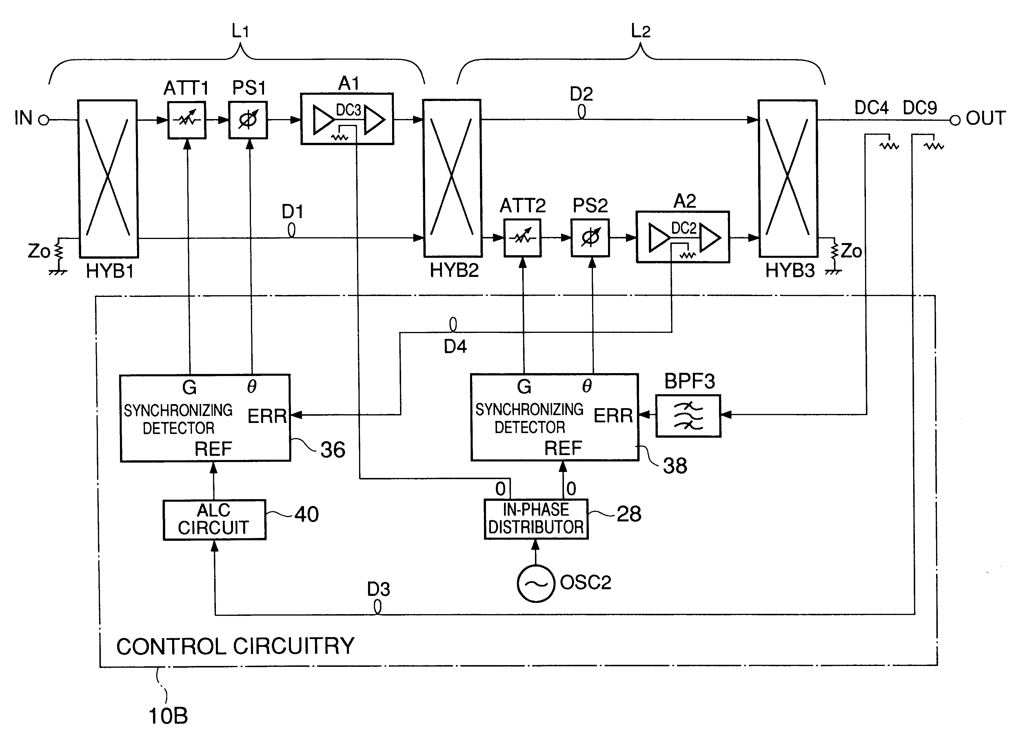
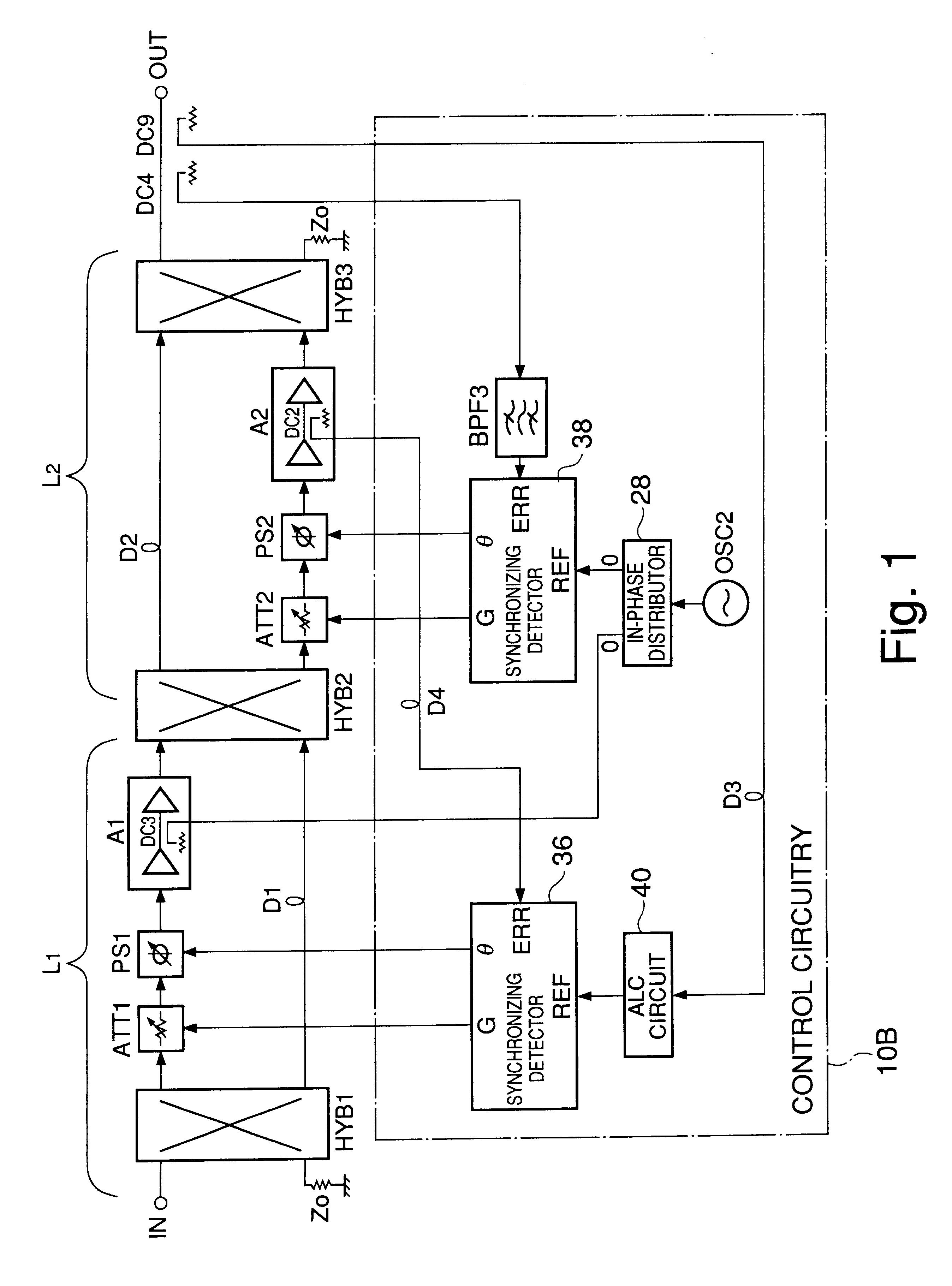
The FF amplifier disclosed in U.S. Pat. No. 5,528,196 is similar to the above-described embodiment in that the pilot signal for L1 is eliminated and the step-by-step procedure under CPU control is no longer necessary. For the purpose of comparison of that art with the device shown in FIG. 1, illustrated in FIG. 9 is a circuit configuration provided by modifying the conventional circuit shown in FIG. 8 through application of the technique disclosed in the above U.S. patent. It should be noted that the illustrated configuration itself is not the invention of the above-mentioned U.S. patent, and, in a strict sense, the circuit of FIG. 9 is a novel structure that is neither disclosed nor suggested in the above patent. The control circuit 10A shown in FIG. 9 includes a differential comparator 16 for optimizing the distortion detection loop L1, and a L2 control unit 18 for optimizing the distortion rejection loop L2.

A first difference between the circuits shown in FIG. 1 and FIG. 9 concer...


PUM


Abstract

An amplifier with feedforward loops for rejecting non-linear distortion and control circuitry for such amplifier and employing a distortion compensation method. A signal from a dominant path is input into a synchronizing detector via an ALC circuit as a reference signal. Using this reference signal, an error signal output from a distortion rejection loop is subjected to synchronizing detection. An offset voltage of a mixer inside the synchronizing detector can be prevented from varying due to change in local level. Outputs from synchronizing detectors are used for control to optimize corresponding loops. As a pilot signal for a distortion detection loop can be eliminated, undesirable spurious effects due to such a pilot signal is avoided. The acquisition time of each of the loops can be shortened because an optimizing control using a step-by-step procedure under CPU control can be eliminated.

Description

1. Field of the InventionThe present invention relates to an amplifier with feedforward (abbreviated hereinafter as FF) loops for rejecting non-linear distortion and control circuitry for optimizing FF loops which employs a method for compensating distortion generated in a main amplifier. The present invention particularly relates to a technique for compensating distortion such as intermodulation distortion generated in a main amplifier.2. Description of Related ArtA base station or a relay station for mobile communications performs wireless transmission of a multicarrier signal including a number of modulated carriers. More specifically, a base station or a relay station modulates each of the multiple carriers and arranges those carriers on a frequency axis at a certain frequency separation to obtain a multicarrier signal. The base station or the relay station then executes radio-frequency amplification (RF amplification) of the obtained multicarrier signal, and performs wireless t...

Claims


Application Information

Patent Timeline
Patent Type & Authority Patents(United States)
IPC IPC(8): H03F1/32H04J1/00
CPCH03F1/3235H03F1/32
Inventor YAMASHITA, KAZUONAKAGAWA, YASUSHIYAMADA, AKIRA
Owner JAPAN RADIO CO LTD
Why Eureka
Try Eureka