Bag with tear-resistant handle

Inactive Publication Date: 2000-05-23
EXOPACK TECH
View PDF16 Cites 56 Cited by
  • Summary
  • Abstract
  • Description
  • Claims
  • Application Information

AI Technical Summary

Benefits of technology

to provide a bag with a handle that resists tearing when the bag is lifted and carried by the handle.
It is another object of the invention to provide a bag with a handle that, before tearing, withstands a high number of impacts by the bag contents against the bottom of the bag interior when the bag is lifted and carried by the handle.
The bag 10 is of a type intended for heavy-duty applications, and is fabricated from a polyolefin sheet or tube stock such as polyethylene having a thickness in the range of 2 to 12 mils. The sheet or tube stock may be coextruded or monoextruded, and may be single ply or multi-ply material. The multi-ply material may be multiple thicknesses of the same sheet or tube stock, or different materials to provide particular characteristics, such as strength, flexibility, UV resistance, or color. The sheet stock may also be woven or non-woven synthetic or non-synthetic material.
A handle 20 is formed in the bag 10 by cutting a slit 21 with a predetermined shape in the bag at a spaced-apart distance from the top end edge 12 and the top elongate seal line 13. To prevent the contents of the bag 10 from spilling out through the handle 20, a bottom elongate seal line 22 is formed by an adhesive, sewing, ultrasonic heating, or other heat-fusing process connecting the thermoplastic walls of the bag 10 together along a narrow, straight line at a spaced-apart distance below the slit 21. The handle 20 is cut to receive one or both hands of a user carrying the bag 10.
As the above table indicates, preferred embodiments of the present invention include three of the four most tear-resistant handles tested using the jolt mechanism. The preferred embodiment of the invention illustrated in FIGS. 1, 2, and 2A, includes the most tear-resistant handle 20 tested, sustaining 45 jolts before tearing. This value is over five times the 8 jolts sustained by the least tear-resistant handle tested. The second preferred embodiment of the invention, illustrated in FIGS. 3 and 3A, includes the handle 31 that sustained 32 jolts before tearing. The third preferred embodiment of the invention, illustrated in FIGS. 4 and 4A, includes the handle 51 that sustained 33 jolts before tearing. Thus, all three preferred embodiments of the invention significantly improve on the tear resistance of prior art bag handles.

Problems solved by technology

Due to the typically heavy weight of these bags and their contents, the force required to lift a bag by its handle when the bag is full or nearly full causes a considerable amount of stress at opposing ends of the handle, and, therefore, on the top end of the bag.
In addition, the contents of the bag may jostle and shift while the bag is being carried by the handle such that the contents repeatedly impact the bottom of the bag interior, imposing more stress on the opposing ends of the handle and the top of the bag.
These lifting and carrying stresses, especially when repeated, can easily tear the handle away from the top end of the bag, causing premature bag rupture and spillage of the bag contents.
Such waste burdens manufacturers, distributors, retailers, and consumers with unnecessary product and packaging replacement and clean-up expenses.

Method used


Image

  • Bag with tear-resistant handle
  • Bag with tear-resistant handle
  • Bag with tear-resistant handle

Examples


Embodiment Construction

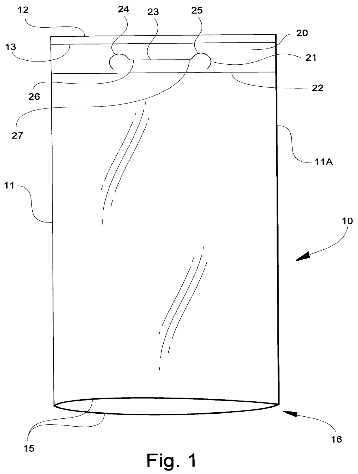
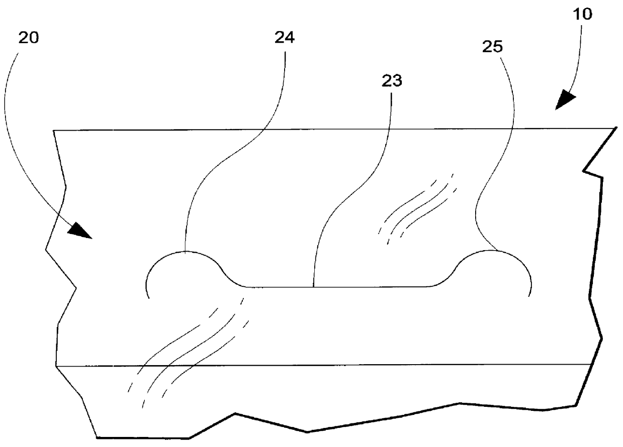
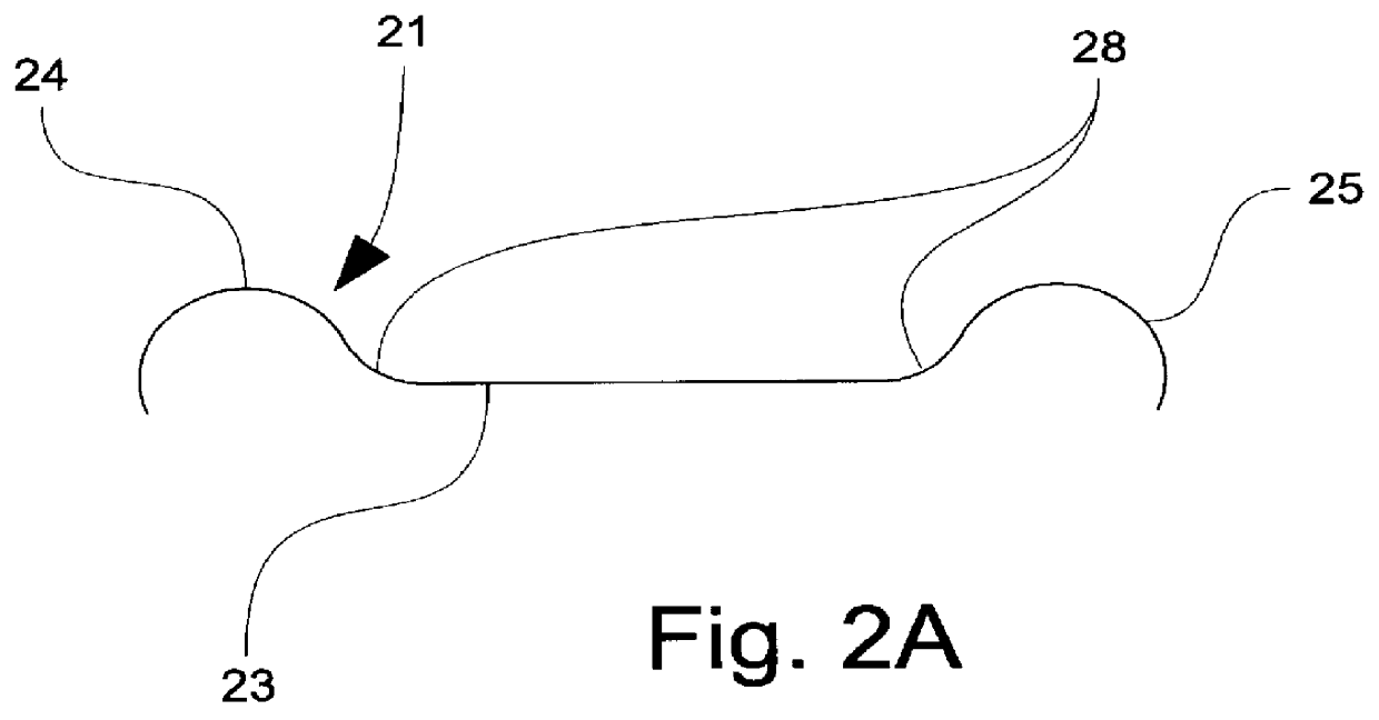
Referring now specifically to the drawings, a bag according to a preferred embodiment of the invention is illustrated broadly at reference numeral 10 in FIGS. 1, 2 and 2A.

The bag 10 is of a type intended for heavy-duty applications, and is fabricated from a polyolefin sheet or tube stock such as polyethylene having a thickness in the range of 2 to 12 mils. The sheet or tube stock may be coextruded or monoextruded, and may be single ply or multi-ply material. The multi-ply material may be multiple thicknesses of the same sheet or tube stock, or different materials to provide particular characteristics, such as strength, flexibility, UV resistance, or color. The sheet stock may also be woven or non-woven synthetic or non-synthetic material.

The bag 10 includes overlying walls defining opposed, joined side edges 11 and 11A, a top end edge 12, and a bottom end edge 15. The term "joined" as used herein is used in its broad sense to mean either two formerly separate sheets connected togeth...


PUM


Abstract

A bag including first and second walls having joined first and second opposed side edges, a top end edge, a bottom end edge, and two spaced-apart seal lines adjacent the top end edge of the bag, the improvement defined of a tear-resistant, bag-supporting handle defined with the two spaced-apart seal lines. The handle includes a hand-insertion slit defined of a middle slit portion parallel to the top end edge and the bottom end edge of the bag and perpendicular to the side edges of the bag, and two arcuate end slit portions, a first end slit portion situated at a first end of the middle slit portion proximate to the first side edge of the bag and a second end slit portion situated at a second end of said middle slit portion proximate to the second side edge of the bag. The end slit portions each define an arc greater than or equal to 180 degrees and extend greater than or equal to 0 degrees and less than or equal to 45 degrees of arc below the middle slit portion toward the bottom end edge of the bag.

Description

TECHNICAL FIELD AND BACKGROUND OF THE INVENTIONThis invention relates to a bag with a tear-resistant handle. The invention relates particularly to the formation of die-cut handles in heavy-duty bags made from single or multiple polyolefin materials, such as LD, HD, and LLD polyethylene, or other thermoplastic material, as well as other woven or nonwoven, synthetic or non-synthetic materials. Such bags are typically used to package materials such as salt, potting soil, small landscaping rocks, pet food, diapers, and similar materials, While the invention has particular application to bags with a capacity of from 10 to 50 pounds, the principle of the invention is applicable to bags of any size and style.Conventional, heavy-duty bags of the prior art typically include a die-cut handle with a single lateral opening for receiving the hand of the user. This prior art design distributes the stress imposed on the bag handle to the top end of the bag. Due to the typically heavy weight of the...

Claims


Application Information

Patent Timeline
IPC IPC(8): B65D33/06B65D33/08
CPCB65D33/08Y10S383/903
Inventor WARR, CHARLES J.
Owner EXOPACK TECH
Why Eureka
Try Eureka