Micromachined acceleration and coriolis sensor

a coriolis sensor and micromachine technology, applied in the direction of acceleration measurement using interia forces, turn-sensitive devices, instruments, etc., can solve the problems of sensor greatly increasing the design complexity, requiring considerable design complexity, and requiring the most volume and power of the approach

Inactive Publication Date: 2000-03-07
KEARFOTT
View PDF15 Cites 109 Cited by
  • Summary
  • Abstract
  • Description
  • Claims
  • Application Information

AI Technical Summary

Problems solved by technology

Since at least three accelerometers are being oscillated simultaneously, this approach usually requires the most volume and power.
This method is not monolithic and considerable complexity of design is needed to make electrical contact with the individual vibrating accelerometers.
The monolithic nature of this structure is advantageous in relation to the benefits of batch micromachining methods but the integration of two proof masses in one sensor greatly increases the design complexity.
This increased complexity imposes design limits that effect sensor performance and fosters a multitude of unwanted parasitic vibrational modes that impair measurement accuracy.
Unfortunately, this second mode operates at the same frequency as the first mode.
This produces an error signal that appears as a false rotation and reduces the accuracy of this type of sensor.
In addition, this type of sensor is often insensitive to linear acceleration and cannot measure rotational and linear motions simultaneously.

Method used


Image

  • Micromachined acceleration and coriolis sensor
  • Micromachined acceleration and coriolis sensor
  • Micromachined acceleration and coriolis sensor

Examples


first embodiment

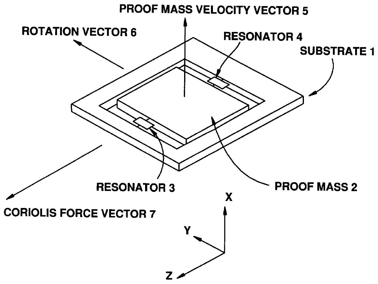
the MAC sensor differs from earlier devices in that the dither motion of the proof mass is perpendicular to the wafer surface instead of parallel. This allows for greater precision in alignment of the forces that produce the dither motion and in the flexure structures that control this motion.

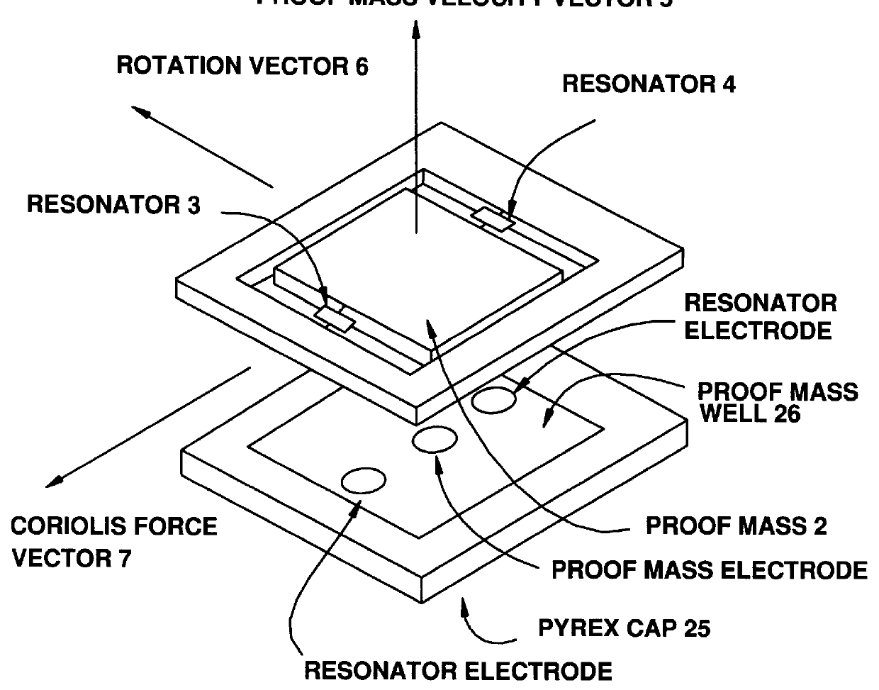
Alternate approaches rely upon external parts, such as magnets and pole pieces, that can effect the alignment of in-plane dither forces. These external parts are sensitive to their mounting structures and can shift or change due to handling and aging of the overall sensor assembly. These effects are reduced in the MAC geometry since the electrostatic plates that determine the perpendicular dither forces are an integral part of each MAC sensor chip.

Another advantage of perpendicular motion relates to the isolation of orthogonal modes of vibration. The frequency of the proof mass in the perpendicular direction is much lower than the in-plane directions. This means the isolation of these modes and...

second embodiment

V. Mechanical Design of a Second Embodiment

In a second embodiment of the present invention, a micromachined sensor is provided for measuring linear and angular motion.

In one particular configuration, the sensor comprises a generally planar substrate, excitation means for vibrating the proof mass at a dither frequency, sensing means for sensing the vibration of the resonators, and means for mounting the excitation means and the sensing means adjacent the proof mass.

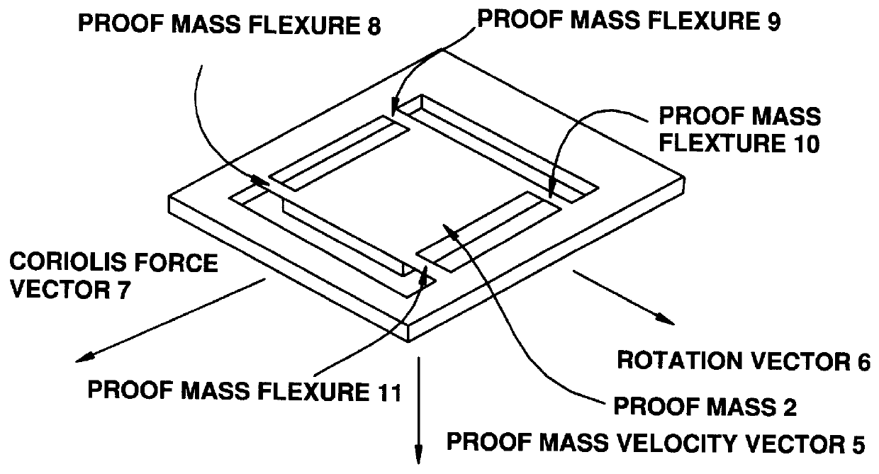
The generally planar substrate is generally aligned in a wafer plane defined by a first axis and a second axis, wherein the second axis is orthogonal to the first axis, wherein the substrate is generally perpendicular to a third axis which is orthogonal to the wafer plane. The substrate is formed to include: a frame or frame-like main body portion having an inner cavity; a proof mass disposed in the inner cavity, the proof mass having a top surface and a bottom surface; a flexural support means for connecting the proof mas...


PUM


Abstract

A solid state silicon micromachined acceleration and Coriolis (MAC) sensor that measures linear and angular motion. The MAC sensor is a single device that performs the functions of a conventional accelerometer and a gyroscope simultaneously. The MAC sensor is unique in that it is a differential dual stage device using only one micromachined proof mass to measure both linear and angular motions. The single proof mass is connected to opposing electromechanical resonators in a monolithic microstructure made from single crystal silicon. This unique design offers improvements in measurement performance and reductions in fabrication complexity that are beyond the state the art of earlier micromachined inertial sensors.

Description

The present invention relates generally to linear and angular motion sensors and, more particularly, to a solid state silicon micromachined acceleration and Coriolis sensor that measures linear and angular motion.DESCRIPTION OF THE PRIOR ARTPrevious attempts to develop inertial multisensors can be divided into three general categories. The first of these consists of a triad of accelerometers that are dithered about a common axis using a rotational or flexural mechanism. Since at least three accelerometers are being oscillated simultaneously, this approach usually requires the most volume and power. This method is not monolithic and considerable complexity of design is needed to make electrical contact with the individual vibrating accelerometers.There is a second approach that uses two oppositely vibrating proof masses and two magnetically driven resonators to sense both rotational and linear motion. This approach uses a monolithic structure that controls the dither motion and the C...

Claims


Application Information

Patent Timeline
IPC IPC(8): G01C19/56G01P15/18G01P15/097G01P15/08G01P15/10
CPCG01C19/56G01P15/0802G01P15/097G01P15/18
Inventor ROSZHART, TERRY V.
Owner KEARFOTT
Why Eureka
Try Eureka