
Method for Operating a Valve Unit and Valve Unit

a valve unit and valve technology, applied in the direction of valve operating means/release devices, mechanical equipment, other domestic objects, etc., can solve the problems of increasing production costs, affecting the operation of valves, and requiring a relatively large number of seals for each piston

Pending Publication Date: 2022-11-03
EUGEN SEITZ
View PDF0 Cites 0 Cited by
  • Summary
  • Abstract
  • Description
  • Claims
  • Application Information

AI Technical Summary

Benefits of technology

The valve unit described in this patent uses a single pilot valve to actuate a piston, which is designed to move quickly. This design allows for optimal response times in blow-molding devices. The piston is also pressure-compensated, which reduces the need for large forces to move it. Overall, the design of the piston allows for a compact and small valve unit.

Problems solved by technology

These valves have the drawback that the space requirement for the piston is relatively large.
The use of two 3 / 2-way valves or one 5 / 2-way valve additionally increases the production costs.
Moreover, these valves require a relatively large number of seals for each piston.
This increases the production and maintenance costs.

Method used


Image

  • Method for Operating a Valve Unit and Valve Unit
  • Method for Operating a Valve Unit and Valve Unit

Examples


Embodiment Construction

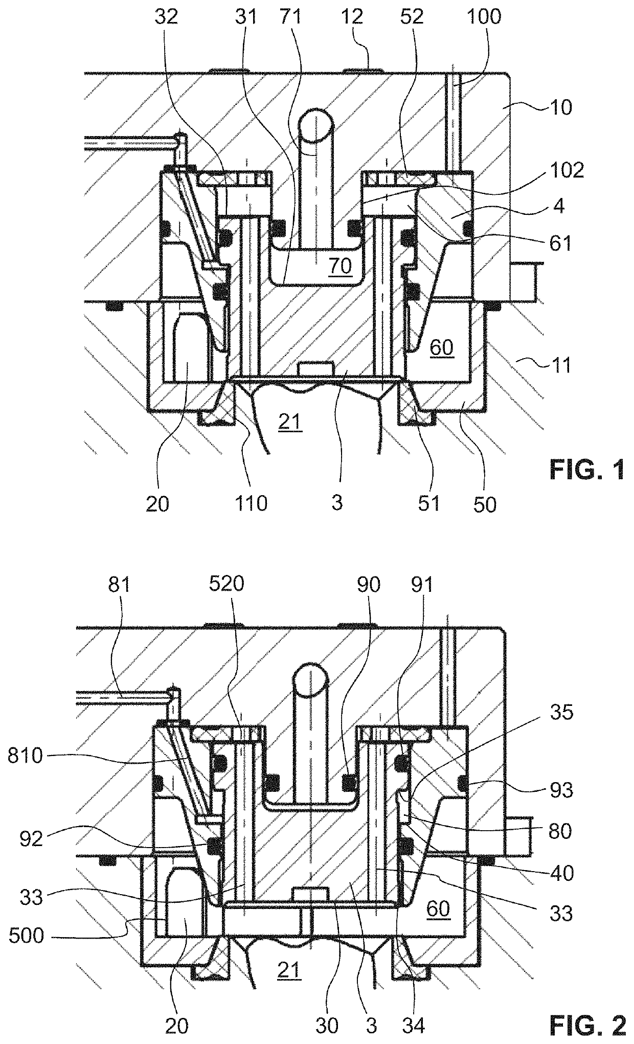
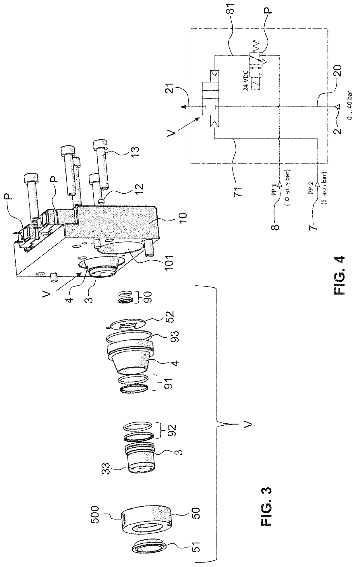
[0043]In FIGS. 1 and 2 a valve unit according to the invention having a process valve, preferably a blowing valve of a blow-moulding machine, is shown. The blowing valve is, for example, a main blowing valve or a pre-blowing valve.

[0044]The valve unit has substantially one piston 3 and one piston receiver in which the piston 3 is movably held and in which valve chambers and control chambers are configured.

[0045]The piston receiver is configured differently depending on the embodiment. The piston receiver is formed, for example, by a separate single-piece or multi-piece housing. In other embodiments, it is part of a control block of a blow-moulding machine. In further embodiments, the piston receiver is, for example, part of a control block and a cover, wherein it comprises further components or only consists of these two components.

[0046]In the example shown here, the piston receiver is formed by a guide apron 4 and a lower housing part 11 and upper housing part 10. The two housing ...


PUM

PropertyMeasurementUnit
pressureaaaaaaaaaa
pressureaaaaaaaaaa
sizeaaaaaaaaaa

Abstract

Method for actuating a valve unit, which has a process pressure inlet, a process pressure outlet and a valve chamber connecting the process pressure inlet to the process pressure outlet and a movable piston for closing and opening the connection between the process pressure inlet and the process pressure outlet. The piston is able to be subjected on a first side to a first control pressure and the piston is able to be subjected on a second side to a second control pressure. The piston is moved by means of the first control pressure and the second control pressure for the purpose of closing and opening the connection. In the operating state of the valve unit, the piston is permanently subjected to the first control pressure, wherein the piston is additionally subjected to the second control pressure for moving the piston in one direction and wherein a pressure which is higher than atmospheric pressure and lower than the second control pressure is used as the first control pressure.

Description

CROSS-REFERENCE TO RELATED APPLICATION[0001]This application claims priority to European Patent Application No. 21 171 205.4 filed Apr. 29, 2021, the disclosure of which is hereby incorporated by reference in its entirety.BACKGROUND OF THE INVENTIONField of the Invention[0002]The present invention relates to a method for operating a valve unit and a valve unit, in particular for pneumatic switching in a blow-moulding process. The valve unit is suitable, in particular, for use in a blow-moulding apparatus for moulding hollow bodies, in particular a stretch blow-moulding machine.Description of Related Art[0003]Blow-moulding apparatuses or blow-moulding machines for moulding hollow bodies are sufficiently well known from the prior art. Generally a pre-heated preform made from a thermoplastic material, preferably made from polyethylene terephthalate (PET), is connected to a blowing nozzle of the blow-moulding machine. The preform is expanded by blowing in a process gas, preferably compr...

Claims


Application Information

Patent Timeline
Patent Type & Authority Applications(United States)
IPC IPC(8): B29C49/42B29C49/78
CPCB29C49/4289B29C49/783B29C49/06B29K2067/003B29L2031/712F16K31/1226F16K31/1223B29C2949/0715
Inventor SCHMIDT, JOACHIM
Owner EUGEN SEITZ
Learn More