
Electromechanical braking system

a technology of electronic mechanical brakes and brake components, which is applied in the direction of brake systems, vehicle sub-unit features, braking components, etc., can solve the problems that the electric brake device 131 may not be able to obtain sufficient energy to generate braking force, and the braking performance of the vehicle may be seriously affected

Pending Publication Date: 2022-10-06
HALDEX VIE (SHANGHAI) ELECTROMECHANICAL BRAKE SYST CO LTD +1
View PDF0 Cites 0 Cited by
  • Summary
  • Abstract
  • Description
  • Claims
  • Application Information

AI Technical Summary

Benefits of technology

The present invention provides an electromechanical brake system with redundant power supply. The system includes at least two control modules, each containing a power supply unit that supplies power to electric brake devices of the corresponding axle. The power supply unit is charged by a recharging power source. The system also includes a redundant power supply structure, which ensures that in case of failure of one power supply unit, the braking performance of the vehicle is not compromised. Additionally, the power supply unit of the control module corresponding to the axle carrying the weight of the vehicle body may be configured as the redundant power supply unit, further ensuring the braking performance of the electric brake device. The technical effect of this invention is to improve the redundancy of power supply network of the brake system and improve the reliability of the electromechanical brake system.

Problems solved by technology

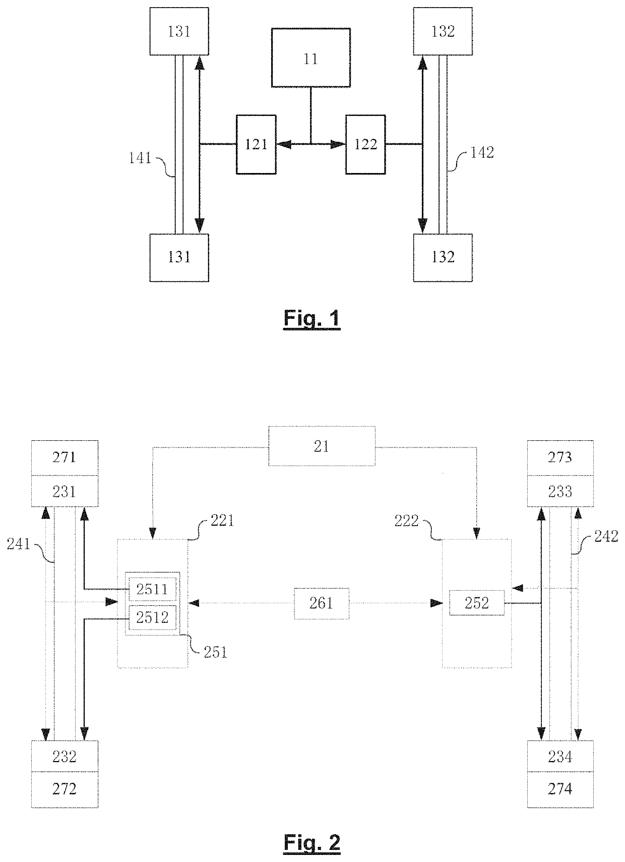
However, when the load of a vehicle with the above-mentioned conventional electromechanical brake system is unbalanced, for example, when the axle 141 bears the main in load of the vehicle, the electric brake device 131 may not be able to obtain sufficient energy to generate braking force if the ultra-capacitor module 121 fails and cannot supply power to the corresponding electric brake device 131.
At this time, since the friction force generated by the wheels at both ends of the axle 142 is limited only by the load of the axle 142, the braking performance of the vehicle may be seriously affected.

Method used


Image

  • Electromechanical braking system
  • Electromechanical braking system
  • Electromechanical braking system

Examples


Embodiment Construction

[0042]The embodiments of the present invention are described in the following detailed description. Other advantages and effects of the present invention will be readily apparent to those skilled in the art from this disclosure. Although the description of the present invention will be described in conjunction with the preferred embodiments, this is not a limitation of the present invention. On the contrary, the invention is described in connection with the embodiments so as to cover other alternatives or modifications that are possible in the embodiments of the present invention, In order to provide a thorough understanding of the present invention, many specific details are included in the following description. The present invention may also be practiced without these details. In addition, some specific details are omitted in the description in order to avoid confusing or obscuring the present invention.

[0043]In the description of the present invention, it should be noted that th...


PUM


Abstract

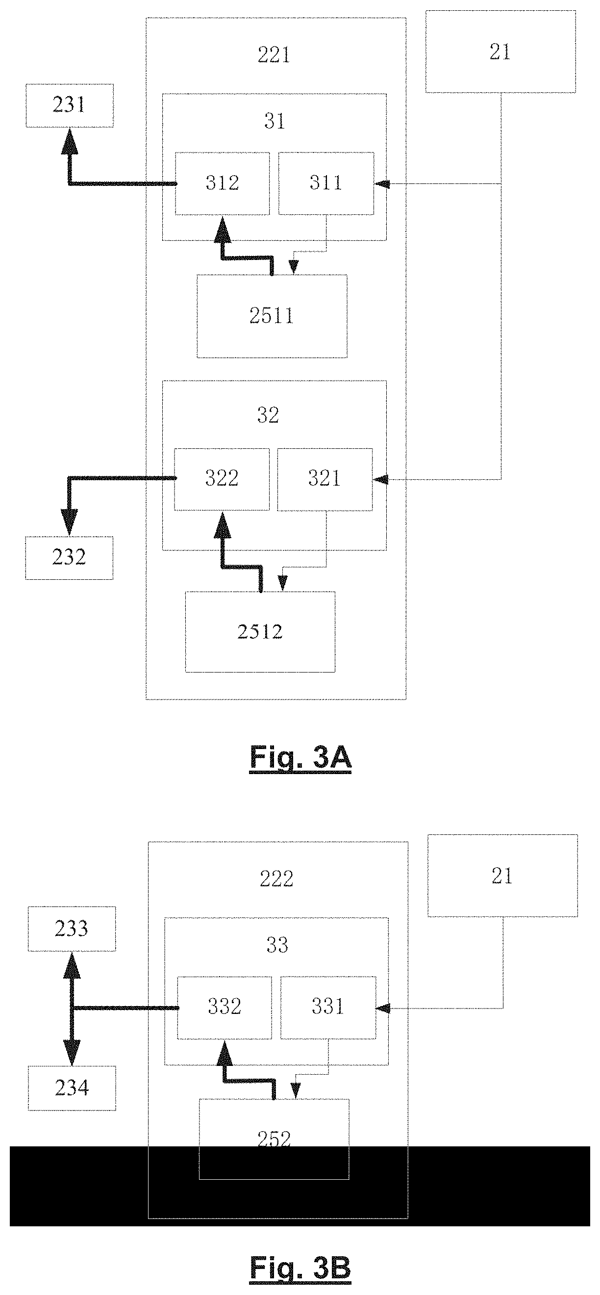
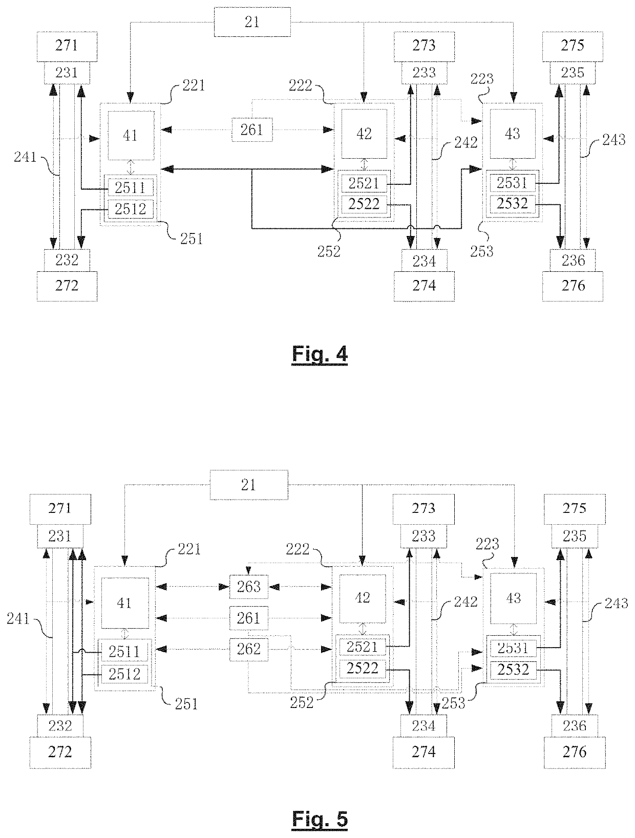
The present invention relates to a braking technology of a vehicle, and in particular to an electromechanical brake (EMB) system with redundant power supply. The electromechanical brake system comprises a recharging power source (21) and at least two control modules (221, 222) corresponding to axles (241, 242) of a vehicle. The control modules (221, 222) comprise a power supply unit (251, 252) that supplies power to electric brake devices (231, 232, 233, 234) disposed at opposite ends of a corresponding axle (241, 242) in response to an operation demand. The power supply unit (251, 252) is charged by the recharging power source (21). The power supply unit (21) of at least one of the control modules (221, 222) is configured with redundancy.

Description

CROSS REFERENCE TO RELATED APPLICATIONS[0001]This application is a continuation of International Application PCT / EP20201085257 with an international filing date of Dec. 9, 2020 and claiming priority to co-pending Chinese Patent Application No. ON 201911331551.5 entitled “An electromechanical brake system”, filed on Dec. 21, 2019.FIELD OF THE INVENTION[0002]The present invention relates to a braking technology of a vehicle, and in particular to an electromechanical brake (EMB) system with redundant power supply.BACKGROUND OF THE INVENTION[0003]An electromechanical brake (EMB) system is an environment-friendly vehicle brake system with simple structure and fast response, which is one of the future development directions of braking technology.[0004]Referring to FIG. 1, FIG. 1 shows a schematic diagram of a conventional electromechanical brake system. As shown in FIG. 1, different from traditional brake system that uses gas or liquid as energy transfer medium, the braking energy of the ...

Claims


Application Information

Patent Timeline
IPC IPC(8): B60T13/74
CPCB60T13/741B60T2270/414B60T2270/413B60T13/74B60T17/18B60T2270/402B60T17/22B60T13/746B60T17/221B60R16/03B60Y2306/13B60Y2400/114B60Y2400/81
Inventor NILSSON, ANDERSLINDQVIST, ANDERS
Owner HALDEX VIE (SHANGHAI) ELECTROMECHANICAL BRAKE SYST CO LTD
Learn More