Drive-driven-unit with coupling/brake combination

A technology of combination device and output components, applied in the combination of coupling and brake, axial brake, brake type and other directions, can solve the problems of crash and damage of machine parts, achieve no waste of structure space, simple and compact space utilization Effect

Active Publication Date: 2009-12-02
CHRISTIAN MAYR GMBH & CO KG
View PDF1 Cites 0 Cited by
  • Summary
  • Abstract
  • Description
  • Claims
  • Application Information

AI Technical Summary

Problems solved by technology

[0006] If the coupling breaks, for example due to external influences, this can cause "crashing" of machine parts arranged behind, which can lead to serious damage
[0007] If the drive motor fails and needs to be dismantled for repair or replacement, then there is the same problem that machine parts set behind can crash

Method used


Image

  • Drive-driven-unit with coupling/brake combination
  • Drive-driven-unit with coupling/brake combination
  • Drive-driven-unit with coupling/brake combination

Examples


Embodiment Construction

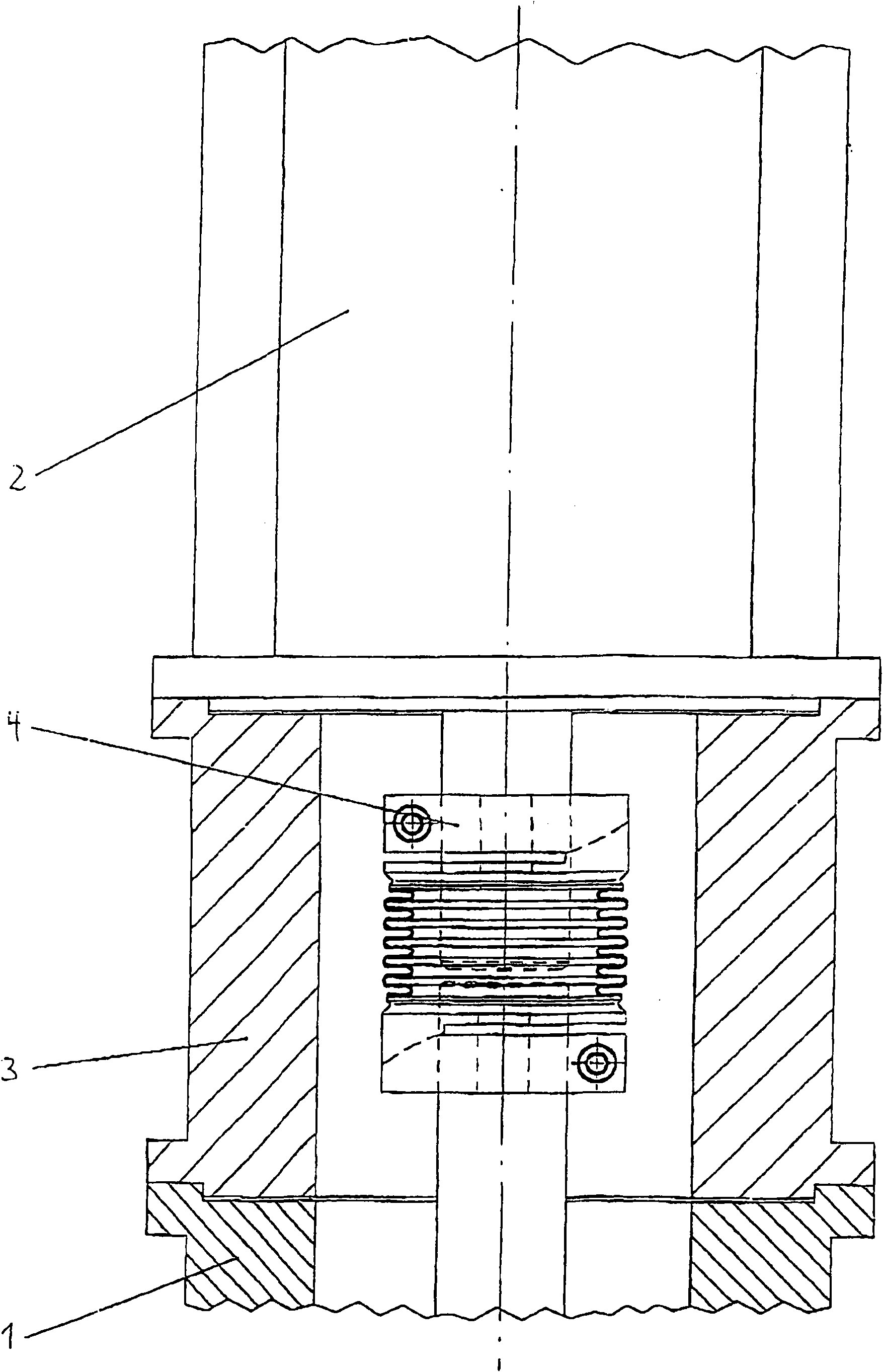
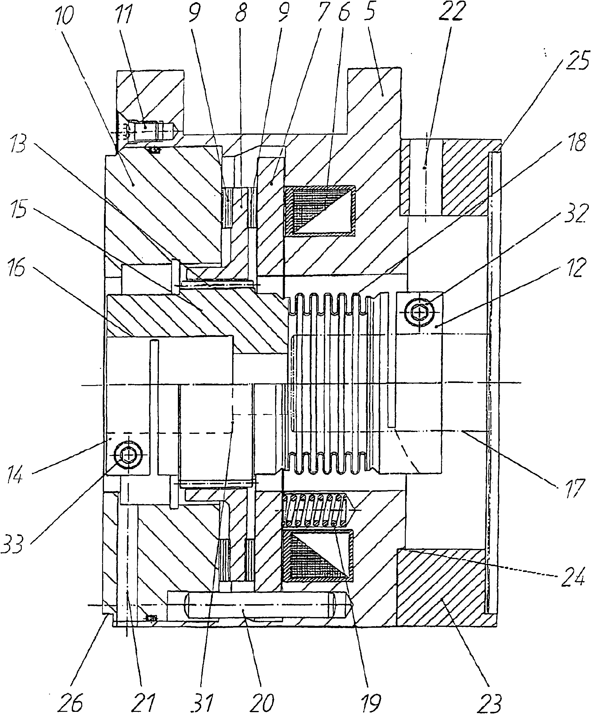
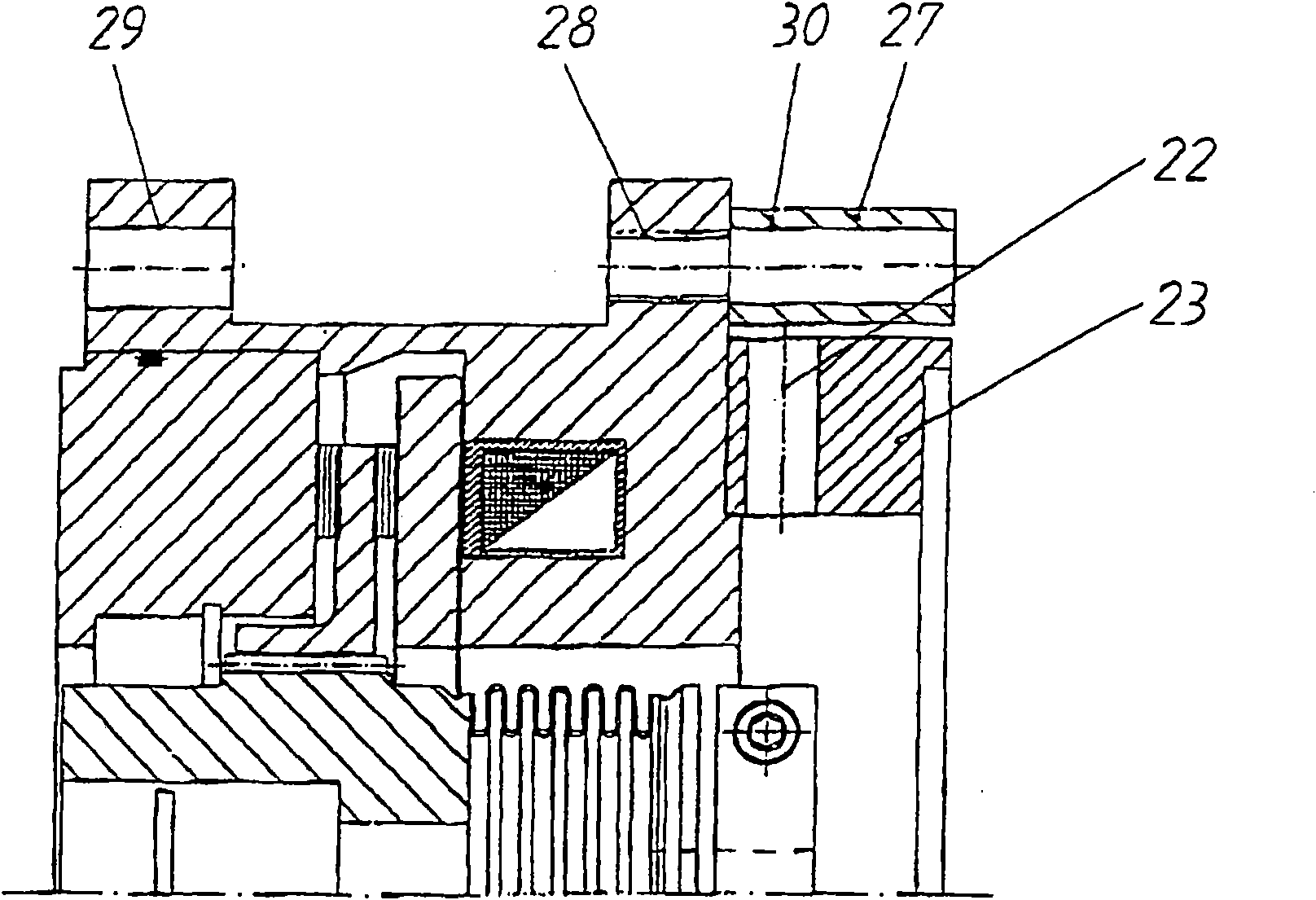
[0029] figure 2 Represents a preferred embodiment of the coupling brake assembly of the present invention, its main feature is that an electrostatic current operated friction brake is built into the "spacer" (= figure 1 In the connecting piece 3), the associated brake rotor 8 is mounted on the meshing teeth 13 on the central hub 15 of the hollow shaft 16 on the output side in the spacer. The shaft head connection not shown in detail on the side.

[0030] The hollow shaft 16 on the output side has an axial extension facing the drive side, which is designed as a flexible coupling, which is designed in particular as a welded bellows coupling with an end lock on the drive side. ring 12, wherein the locking ring 12 can be operated with a clamping screw 32.

[0031] exist figure 2 The hollow shaft 16 completely surrounding the output side and the bellows coupling 18 on the drive side are equivalent to figure 1 The outer housing of the connecting piece 3 or the spacer is also d...


PUM


Abstract

The invention relates to a drive-driven-unit with a coupling / brake combination, characterised in that the unit is embodied as a so-called lantern (connector piece) with integrated static current operated spring pressure brake and with a central hub (for example, a bellows coupling or a plug-in coupling or a shaft in hollow shaft) between the input side (motor) and output side (gearbox / spindle / or similar) and the brake is arranged on the output side (gearbox / spindle side). The unit is embodied such that both shaft levels from the input side (motor) and output side (gearbox / spindle / or similar) lie directly adjacent each other in the central hub such that the shortest possible length of the whole unit can be achieved.

Description

[0001] This application is a divisional application of the Chinese invention patent application with the application number "200480019245.3". The original application (Chinese application number "200480019245.3") is an international application, its international application number is "PCT / EP2004 / 008654", the application date is August 2, 2004, and the invention name is "coupling system moving combination device". technical field [0002] The invention relates to a drive input and output assembly with a coupling brake assembly. Background technique [0003] The invention is based on the prior art as described in DE 201 05 746.8 or WO 02 / 084841 of the applicant. [0004] In these known designs, an elastic coupling, for example a bellows coupling or a plug-in coupling with an elastic star, is usually installed between the motor shaft and the gearbox shaft or the main shaft of the drive, And the whole is shielded from the outside world through a connection of a so-called spac...

Claims


Application Information

Patent Timeline
Patent Type & Authority Applications(China)
IPC IPC(8): F16D67/00F16D65/14F16D55/28F16D55/00F16D65/18
CPCF16D67/00F16D2055/0058F16D2121/22
Inventor H·福格特J·艾伯勒L·布劳恩
Owner CHRISTIAN MAYR GMBH & CO KG
Why Eureka
Try Eureka