Braking control device for vehicle

a technology for controlling devices and vehicles, applied in the direction of brake systems, braking components, transportation and packaging, etc., can solve the problems of limited regenerative braking force of regenerative generators, and achieve the effect of ensuring steering stability of vehicles

Pending Publication Date: 2022-10-06
ADVICS CO LTD
View PDF0 Cites 0 Cited by
  • Summary
  • Abstract
  • Description
  • Claims
  • Application Information

AI Technical Summary

Benefits of technology

[0008]In the braking control device for a vehicle according to the invention, the controller (ECU) is configured to regulate the front and rear wheel friction braking forces (Fmf and Fmr) based on a normative regenerative force (Fz) corresponding to a rotation speed equivalent value (Ns) equivalent to a rotation speed (Ng) of the regenerative generator (GN). According to the above configuration, since the front and rear wheel friction braking forces Fmf and Fmr are regulated according to an operating state (that is, the rotation speed equivalent value Ns) of the generator GN, energy regeneration can be appropriately performed.
[0009]In the braking control device for a vehicle according to the invention, the controller (ECU) is configured to: when the regenerative braking force (Fg) does not reach the normative regenerative force (Fz), set both the front and rear wheel friction braking forces (Fmf and Fmr) to zero, and when the regenerative braking force (Fg) reaches the normative regenerative force (Fz), increase the rear wheel friction braking force (Fmr) from zero before increasing the front wheel friction braking force (Fmf) from zero. According to the above configuration, since a front-rear distribution of the braking force acting on an entire vehicle including the friction braking force and the regenerative braking force is appropriately regulated, steering stability of the vehicle can be secured.
[0011]In the braking control device for a vehicle according to the invention, the controller (ECU) is configured to regulate the front and rear wheel friction braking forces (Fmf and Fmr) based on a normative regenerative force (Fz) corresponding to a rotation speed equivalent value (Ns) equivalent to a rotation speed (Ng) of the regenerative generator (GN). According to the above configuration, since the front and rear wheel friction braking forces Fmf and Fmr are regulated according to an operating state (that is, the rotation speed equivalent value Ns) of the generator GN, energy regeneration can be appropriately performed.
[0012]In the braking control device for a vehicle according to the invention, the controller (ECU) is configured to: when the regenerative braking force (Fg) does not reach the normative regenerative force (Fz), set both the front and rear wheel friction braking forces (Fmf and Fmr) to zero, and when the regenerative braking force (Fg) reaches the normative regenerative force (Fz), increase the front wheel friction braking force (Fmf) from zero before increasing the rear wheel friction braking force (Fmr) from zero. According to the above configuration, since a front-rear distribution of the braking force acting on an entire vehicle is regulated appropriately, steering stability of the vehicle can be secured.

Problems solved by technology

However, a regenerative braking force of a regenerative generator (which is also an “electric motor for traveling”) is limited by rating of a power transistor (IGBT or the like) that drives the regenerative generator, battery charge acceptance, and the like.

Method used


Image

  • Braking control device for vehicle
  • Braking control device for vehicle
  • Braking control device for vehicle

Examples


first embodiment

of Braking Control Device for Vehicle

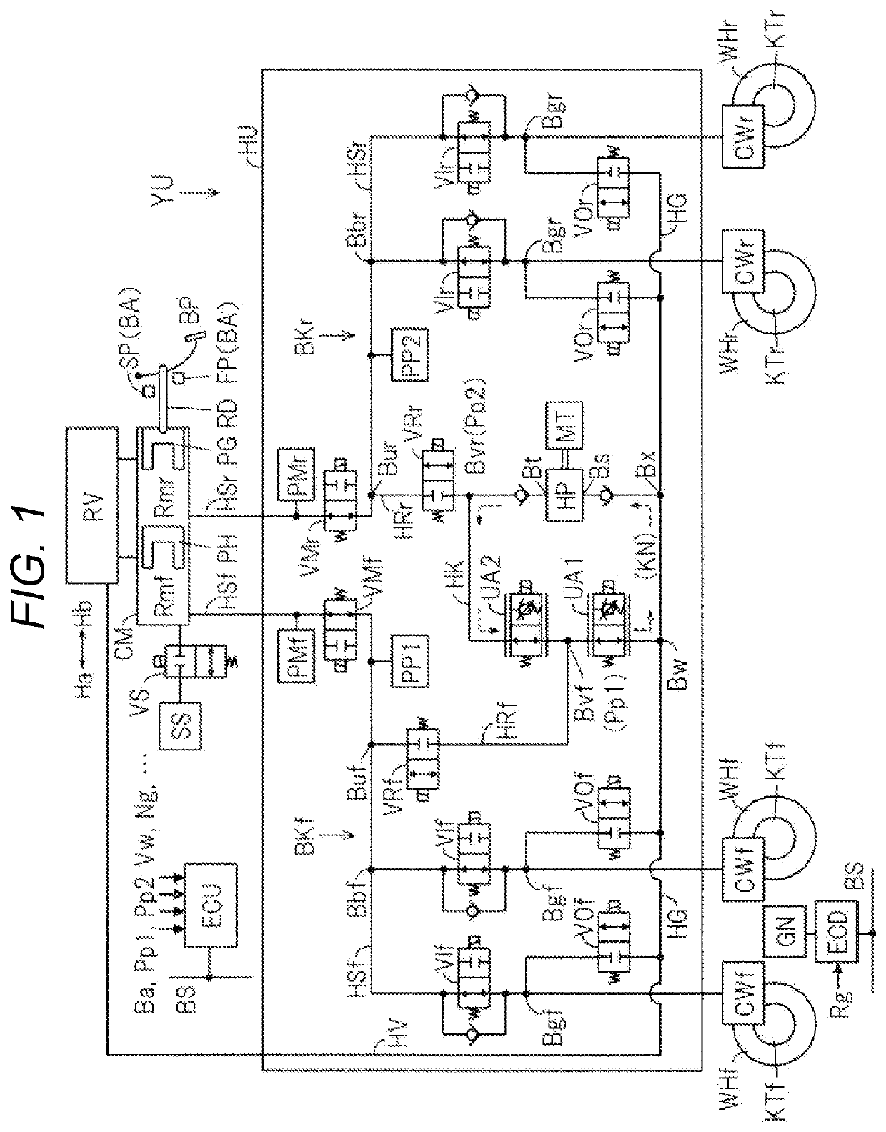
[0021]A braking control device SC according to a first embodiment of the invention will be described with reference to an overall configuration diagram in FIG. 1. In the first embodiment, in a two-system fluid path (braking systems), a front wheel braking system BKf is connected to wheel cylinders CWf of front wheels WHf, and a rear wheel braking system BKr is connected to wheel cylinders CWr of rear wheels WHr. That is, a front-rear type (also referred to as “type II”) fluid path is used as the two-system fluid path.

[0022]The front wheel WHf of the vehicle is provided with an electric motor GN for driving (traveling). That is, the vehicle is an electric vehicle such as a hybrid vehicle or an electric vehicle. The electric motor GN for traveling also functions as a generator (electric generator) for energy regeneration. The electric motor / generator GN is controlled by a drive controller ECD. In the braking control device SC, a regenerative cooper...


PUM


Abstract

A braking control device is applied to, for example, a vehicle in which a regenerative braking force is generated on a front wheel by a regenerative generator provided on the front wheel. The braking control device includes an actuator configured to individually generate a front wheel friction braking force on the front wheel and a rear wheel friction braking force Fmr on a rear wheel of the vehicle; and a braking controller configured to control the actuator. In the braking control device, the braking controller is configured to regulate the front and rear wheel friction braking forces based on a normative regenerative force corresponding to a rotation speed equivalent value equivalent to a rotation speed of the regenerative generator.

Description

TECHNICAL FIELD[0001]The present disclosure relates to a braking control device for a vehicle.BACKGROUND ART[0002]PTL 1 discloses that, in order to “reduce total power consumption by reducing power consumption of a brake motor of an electric friction brake while maintaining a balance between generation and consumption of electrical energy in an auxiliary battery”, “a restriction flag is turned on and a start of the brake motor is prohibited during a period from the start of the brake motor to when a set time period elapses”.[0003]PTL 1 discloses that “When an actual regenerative braking force Fm* is less than a required total braking force Fsref, a request for operating a friction brake (including a hydraulic brake 44 and an electric brake 40) is issued. A required friction braking force Faref is determined based on a value (Fsref−Fm*) obtained by subtracting the actual regenerative braking force Fm* from the required total braking force Fsref. When the required friction braking for...

Claims


Application Information

Patent Timeline
Patent Type & Authority Applications(United States)
IPC IPC(8): B60L7/26B60T13/58B60T8/17
CPCB60L7/26B60T13/586B60T8/17B60T2240/00B60T2270/604B60T1/10B60L2240/421B60L2240/423B60L15/2009B60L7/18F16D61/00
Inventor YAMAMOTO, TAKAYUKIYOGO, KAZUTOSHI
Owner ADVICS CO LTD
Why Eureka
Try Eureka