
Cutting tool

a cutting tool and cutting technology, applied in the field of cutting tools, can solve the problems of insufficient biting property and poor chip discharge property of work materials, and achieve the effect of improving both the biting property of work materials and the chip discharge property

Pending Publication Date: 2022-10-06
TUNGALOY CORP
View PDF0 Cites 0 Cited by
  • Summary
  • Abstract
  • Description
  • Claims
  • Application Information

AI Technical Summary

Benefits of technology

The present invention provides a cutting tool that improves both the biting and chip discharge properties. This is achieved by configuring the drill body with multiple cutting edges and a first tip portion. Additionally, the drill body includes a first core thickness portion and a second core thickness portion. With this design, a better grip on the work material can be achieved while also facilitating the removal of chips during the cutting process.

Problems solved by technology

However, although the 4 flute drill of the prior art is capable of drilling holes in the work material with high machining efficiency, in order to ensure the strength of the drill tip and because thinnings easily interfere with each other due to the large number of edges, the chisel becomes larger (the chisel edge becomes thicker) than that of a 2 flute drill, and as a result, the biting property to the work material is yet insufficient.
Also, in the 4 flute drill of the prior art, since the width of one flute groove is inevitably narrower than that of a normal 2 flute drill, the volume of the flute groove is relatively small, and as a result, resulting in poor chip discharge property.

Method used


Image

  • Cutting tool
  • Cutting tool
  • Cutting tool

Examples


embodiment

Actions and Effects of Embodiment

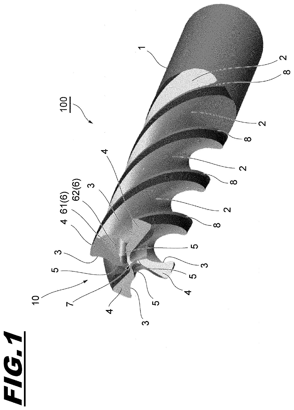
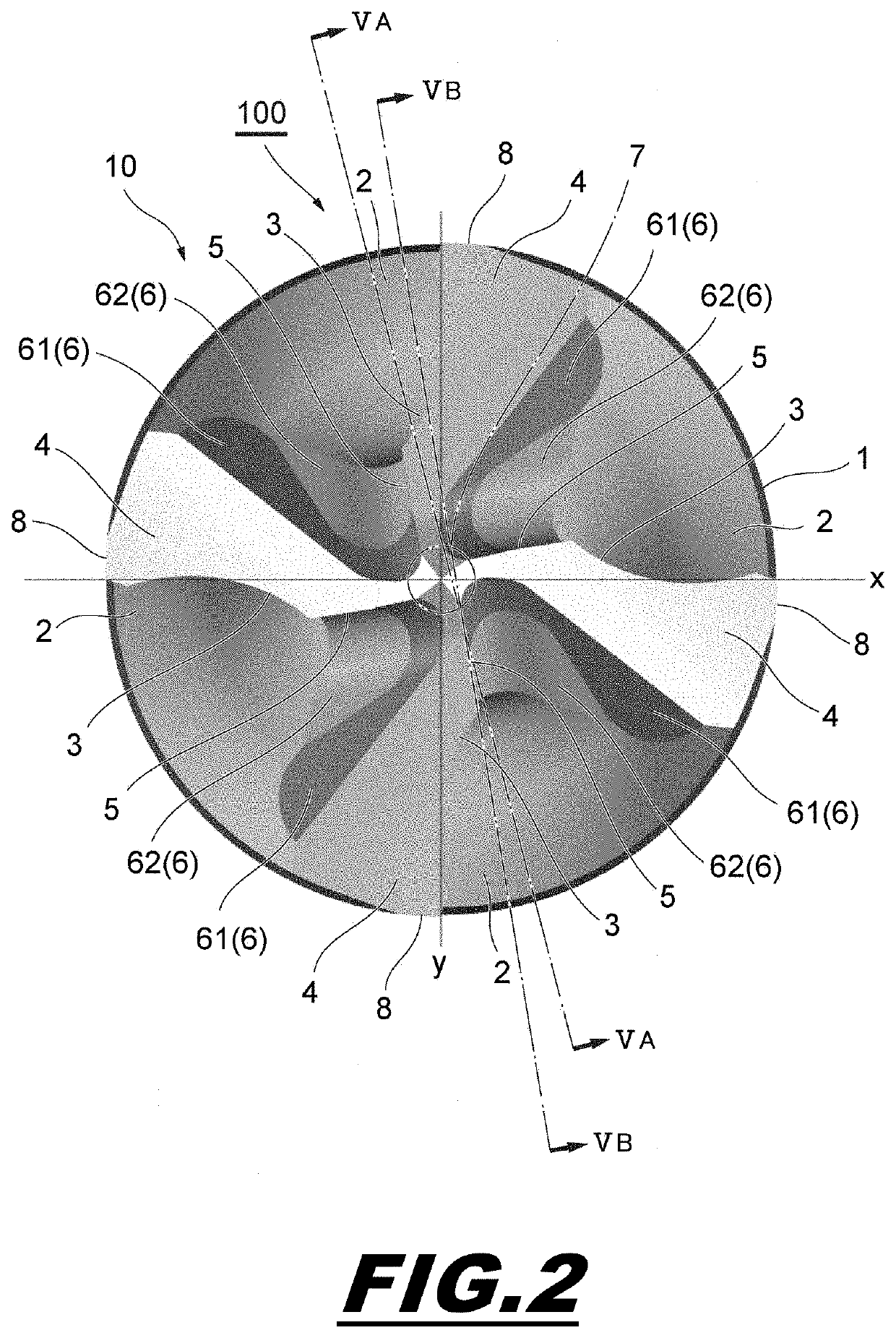
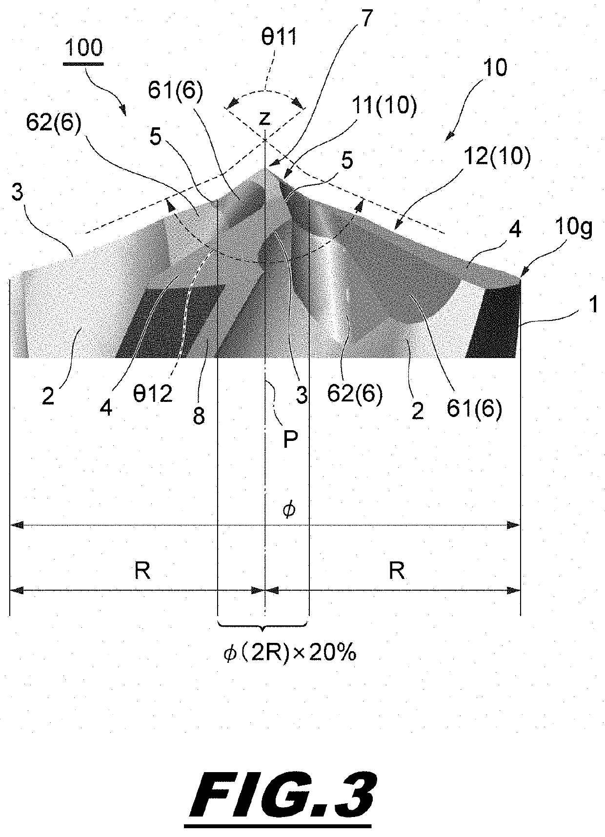
[0042]According to the 4 flute drill 100 configured in this manner, the thinning cutting edge 5 formed by the thinning portion 6 has a larger rake angle than the original chisel edge, and has a larger volume of the thinning pocket for discharging chips generated during the hole cutting of the work material. Thus, the cutting resistance and biting property to the work material and the chip discharge property can be improved. Further, in the hole cutting process, since the first tip portion 11 located at the one end portion 10 of the drill body 1 and having the relatively small (sharp) tip angle θ11 first comes into contact with the work material, the biting property to the work material can be enhanced sufficiently even if the chisel edge 7 tends to be larger than that of a 2 flute drill. In addition, since the position corresponding to each main cutting edge 3 on the outer peripheral surface of the drill body 1 is provided with the margin 8 in the ve...


PUM


Abstract

Provided is a cutting tool capable of improving both the biting property to a work material and the chip discharge property. The cutting tool includes a drill body rotated about a central axis, four or more cutting edges formed on one end portion of the drill body to face a forward side of a rotation direction, and a flute groove that is formed between the cutting edges adjacent to each other in a circumferential direction and extends substantially spirally along the central axis. (1) The one end portion includes a first tip portion that includes the central axis and has a first tip angle, and a second tip portion that extends from the first tip portion to an outer peripheral edge of the drill body and has a second tip angle larger than the first tip angle, and (2) the drill body includes a first core thickness portion that is formed in such a manner that a core thickness thereof gradually decreases from the one end portion to the other end portion, and a second core thickness portion that is formed in such a manner that a core thickness thereof is constant from the first core thickness portion toward the other end portion.

Description

BACKGROUNDField[0001]The present invention relates to a cutting (drilling) tool with four or more drill blades that is excellent in both biting property to a work material and chip discharge property.Description of Related Art[0002]As a means for improving the machining efficiency of a work material by a drill, there has conventionally been proposed a 4 flute drill having twice the number of blades as a normal 2 flute drill (see Patent Publication JP-A-2019-048347). The 4 flute drill of the prior art is intended to improve the biting property to the work material and suppress burrs from forming toward a back surface of the work material, and has the following configuration. In other words, on a tip surface of such a 4 flute drill, the four blades are composed of two parent cutting edges that are continuous from a radially outer peripheral end portion toward the center and two child cutting edges that are located between the parent cutting edges in a circumferential direction and con...

Claims


Application Information

Patent Timeline
IPC IPC(8): B23B51/02
CPCB23B51/02B23B2251/40B23B2251/04B23B2251/18B23B51/00B23B2251/204B23B2251/402B23B2251/188B23B2251/182B23B2251/408
Inventor HORI, ISSEI
Owner TUNGALOY CORP
Learn More