Fuel cell system

a fuel cell and system technology, applied in the field of fuel cell systems, can solve the problems of increasing the number of parts and the weight, and achieve the effect of efficiently humidifying the oxidizer gas withou and efficiently humidifying the reaction gas

Pending Publication Date: 2022-09-29
HONDA MOTOR CO LTD
View PDF5 Cites 0 Cited by
  • Summary
  • Abstract
  • Description
  • Claims
  • Application Information

AI Technical Summary

Benefits of technology

[0014]According to this aspect, it is possible to efficiently humidify the oxidizer gas without increasing the number of parts.
[0015]Thus, according t

Problems solved by technology

However, when the hot water raiser is provided in this

Method used


Image

  • Fuel cell system
  • Fuel cell system
  • Fuel cell system

Examples


Embodiment Construction

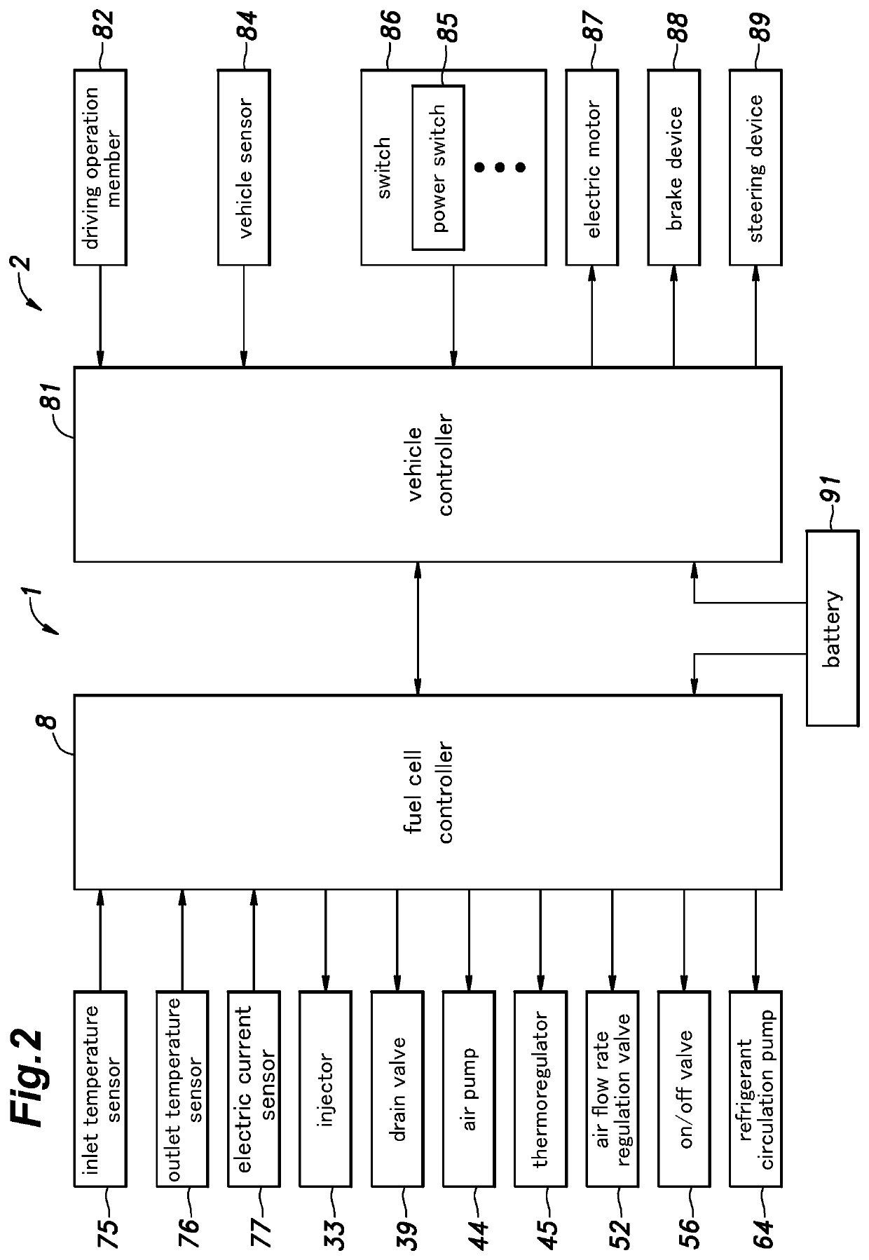
[0021]In the following, a fuel cell system 1 according to an embodiment of the present invention will be described. The fuel cell system 1 is mounted on a vehicle 2. As shown in FIG. 1, the fuel cell system 1 includes a fuel cell stack 4, a fuel gas supply device 5 as a fuel gas supply unit configured to supply a fuel gas to the fuel cell stack 4, an oxidizer gas supply device 6 as an oxidizer gas supply unit configured to supply an oxidizer gas to the fuel cell stack 4, a refrigerant supply device 7 configured to supply a refrigerant to the fuel cell stack 4, and a fuel cell controller 8. In the present embodiment, the fuel gas is a hydrogen gas, and the oxidizer gas is air. The fuel gas and the oxidizer gas may be also referred to as “reaction gas”. The fuel gas supply device 5 and the oxidizer gas supply device 6 constitute a reaction gas supply unit. Further, the oxidizer gas supply device 6 constitutes an oxidizer gas supply unit.

[0022]The fuel cell stack 4 includes a plurality...


PUM


Abstract

A fuel cell system includes: a reaction gas supply unit configured to supply a reaction gas to a fuel cell stack; a humidifier configured to transfer moisture from an off-gas discharged from the fuel cell stack to the reaction gas; and a controller configured to control the reaction gas supply unit so as to regulate a supply amount of the reaction gas, wherein the controller is configured to acquire a temperature of the humidifier and set the supply amount of the reaction gas based on a target power generation amount of the fuel cell stack, and in a case where the temperature of the humidifier is equal to or lower than a prescribed warm-up determination value, the controller executes warm-up control to increase the supply amount of the reaction gas as compared with a case where the temperature of the humidifier is higher than the warm-up determination value.

Description

TECHNICAL FIELD[0001]The present invention relates to a fuel cell system.BACKGROUND ART[0002]JP2004-165062A discloses a humidifier that transfers moisture between a reaction gas supplied to a fuel cell stack and an off-gas discharged from the fuel cell stack and thus humidifies the reaction gas. An appropriate amount of moisture contained in the reaction gas suppresses the deterioration of the fuel cell stack. The humidifier is provided with a hot water raiser so as to increase a temperature of the reaction gas. By increasing the temperature of the reaction gas in the humidifier, the saturated vapor pressure increases, and thus the amount of moisture the reaction gas can contain increases.[0003]However, when the hot water raiser is provided in this way, the number of parts and the weight may increase.SUMMARY OF THE INVENTION[0004]In view of the above background, an object of the present invention is to provide a fuel cell system that can efficiently humidify a reaction gas without i...

Claims


Application Information

Patent Timeline
IPC IPC(8): H01M8/04119H01M8/04223H01M8/04858H01M8/04746
CPCH01M8/04126H01M8/04268H01M8/0491H01M8/04253H01M8/04753H01M2250/20H01M8/04492H01M8/0432
Inventor AKABORI, SHOSATO, SHUJIINOUE, TOMOYUKI
Owner HONDA MOTOR CO LTD
Why Eureka
Try Eureka