Magnetic sensor
a technology of magnetic sensors and magnets, applied in the field of magnetic sensors, can solve the problem of weak capability of magnetic sensors, and achieve the effect of expanding its us
- Summary
- Abstract
- Description
- Claims
- Application Information
AI Technical Summary
Benefits of technology
Problems solved by technology
Method used
Image

Examples
example 1
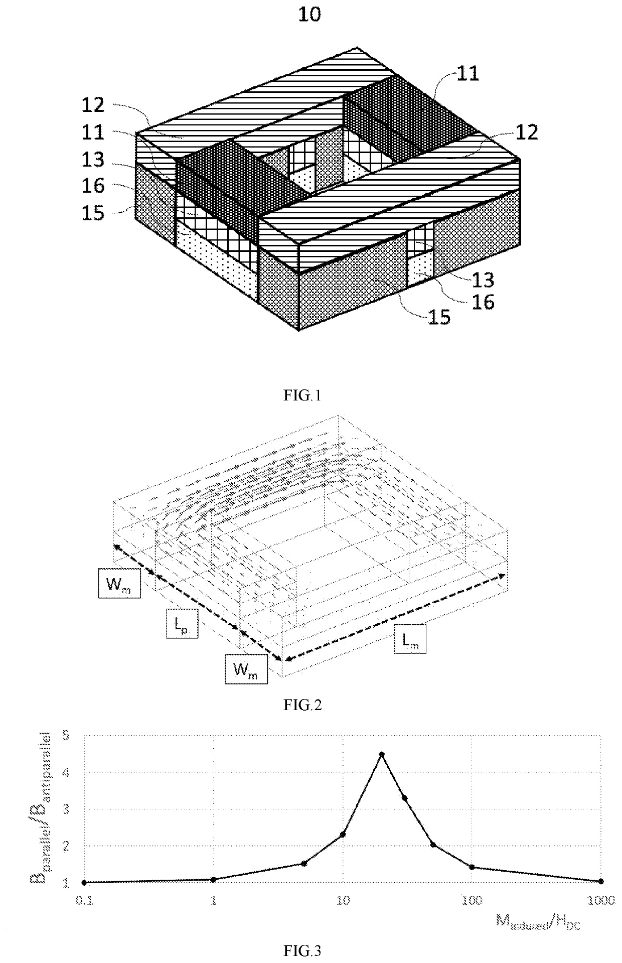
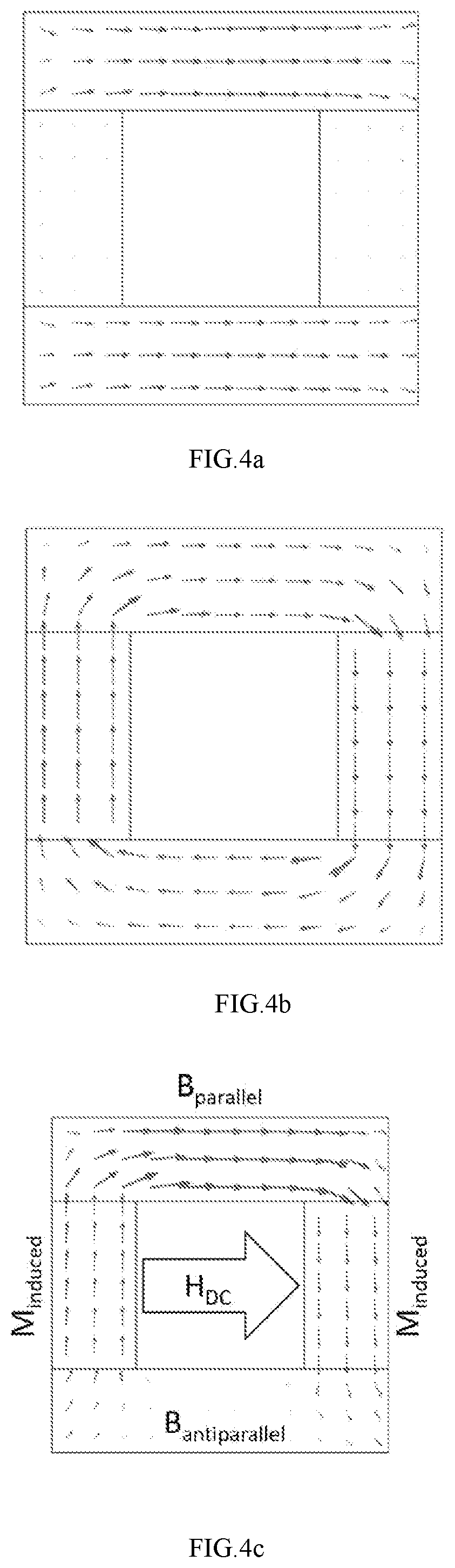
[0053]FIGS. 1-5 show the structure, working principle, and magnification of the magnetic sensor 10 of Example 1, respectively. In this example, the first magnetostrictive element and the second magnetostrictive element are arranged on the normal side of the first piezomagnetic element and the second piezomagnetic element, respectively, and the first magnetostrictive element, the second magnetostrictive element, the first piezomagnetic element and the second piezomagnetic element are arranged on the identical horizontal layer, thereby forming the rectangular magnetic induction layer, which has the length and width consistent with each other (as shown in FIG. 2), that is, during detailed design, we can set the length of the first magnetostrictive element and the second magnetostrictive element as Lm, the width of them as Wm, and the length of the first piezomagnetic element and the second piezomagnetic element as Lp, so as to attain Lm=Lp+2Wm.
[0054]It can be understood that Lm among t...
example 2
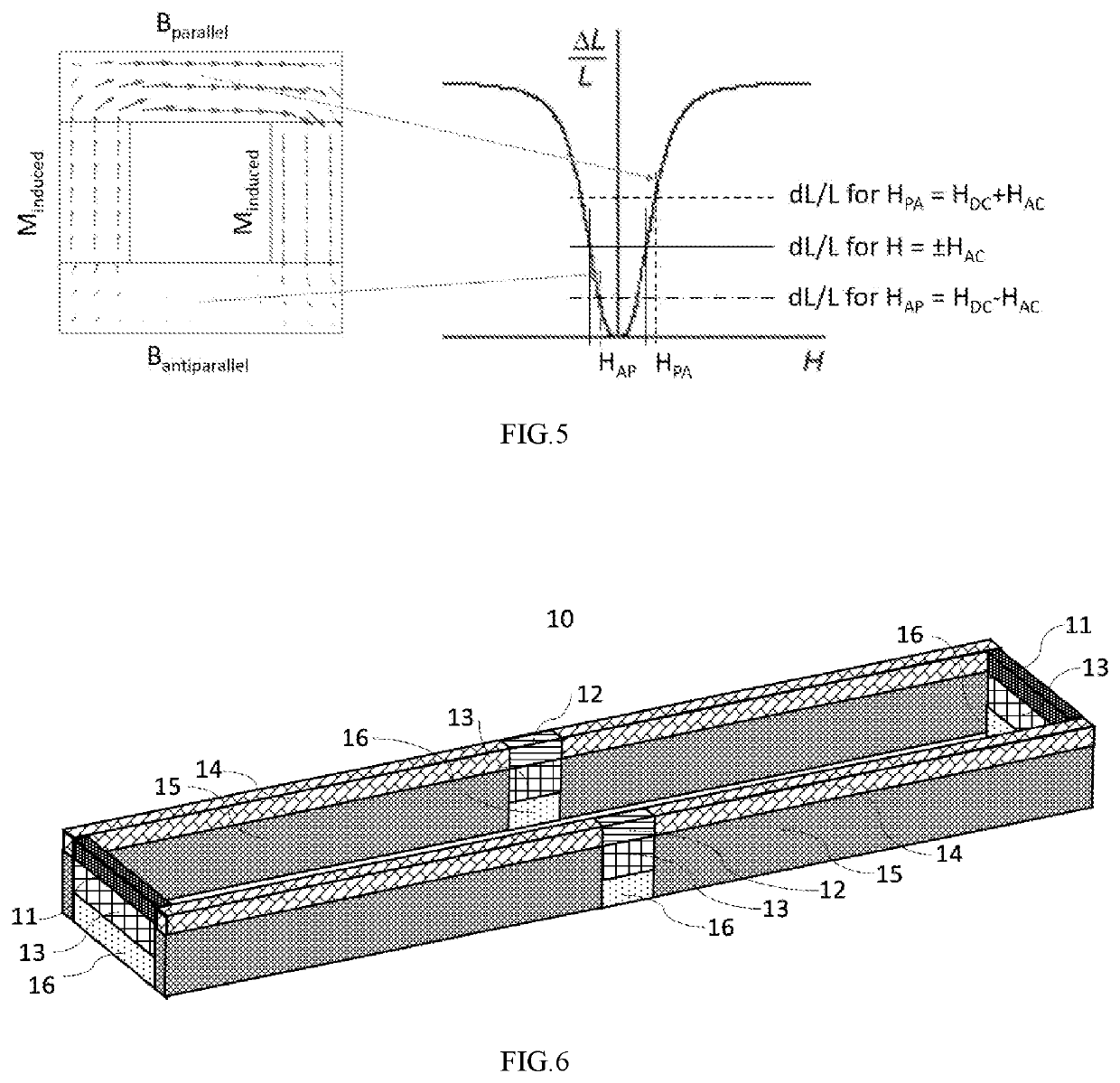
[0061]In order to further increase the magnification of the measured magnetic field HDC, thereby making the sensor have sensitivity covering a lower magnetic field, Lm can be increased, while Lp and Wm can be decreased. Specifically, FIGS. 6-9 are schematic diagrams of the structure and magnification of the magnetic sensor 10 in Example 2, respectively, where as same as Example 1, the first magnetostrictive element and the second magnetostrictive element are arranged on the normal side of the first piezomagnetic element and the second piezomagnetic element, respectively, and the first magnetostrictive element, the second magnetostrictive element, the first piezomagnetic element and the second piezomagnetic element are arranged on the identical horizontal layer, thereby forming a rectangular magnetic induction layer, in addition, the magnetic conductor element 14, which is preferably made of high-magnetoconductivity material (with low or negligible magnetostriction), is arranged on t...
example 3
[0067]FIGS. 10-12 are schematic diagrams of the structure and magnification of the magnetic sensor 10 in Example 3, respectively, where the highest magnification of the measured magnetic field HDC and the simplification of the structure have been achieved. Specifically, the first magnetostrictive element and the second magnetostrictive element are arranged on the same side of the first piezomagnetic element and the second piezomagnetic element, respectively, and the first magnetostrictive element is arranged on the first piezomagnetic element and the second magnetostrictive element is arranged on the second piezomagnetic element, to form a magnetic induction strip. Compared with Examples 1 and 2 described above, the magnetic circuit is replaced by two “vertical” magnetic circuits, and the circuit has its bottom composed of the piezomagnetic component 11, and the induced magnetization intensity controlled by the piezoelectric component 13 underneath it. The magnetostrictive element 1...
PUM
 Abstract
Description
Claims
Application Information
 - R&D
- Intellectual Property
- Life Sciences
- Materials
- Tech Scout
- Unparalleled Data Quality
- Higher Quality Content
- 60% Fewer Hallucinations
Browse by: Latest US Patents, China's latest patents, Technical Efficacy Thesaurus, Application Domain, Technology Topic, Popular Technical Reports.
© 2025 PatSnap. All rights reserved.Legal|Privacy policy|Modern Slavery Act Transparency Statement|Sitemap|About US| Contact US: help@patsnap.com