Brake system and method for controlling a brake system

a brake system and brake technology, applied in the direction of braking systems, braking components, transportation and packaging, etc., can solve the problems of unfavorable braking distance, complex arrangement of four or five pistons and six solenoid valves, and high construction length

Pending Publication Date: 2022-08-11
IPGATE
View PDF0 Cites 1 Cited by
  • Summary
  • Abstract
  • Description
  • Claims
  • Application Information

AI Technical Summary

Benefits of technology

The invention is a brake system for autonomous and electric vehicles that improves safety and efficiency. It is designed to be compact, with a small overall volume and redundancies for pressure generation, electrical supply, and failure of the pump motor of the ABS / ESP unit. It also enables an ABS function even in the event of failure of the ESP unit, improving the braking distance. Additionally, it provides individual control for each axle, allowing for better braking performance.

Problems solved by technology

The trend towards vehicles with autonomous driving places high demands on the brake system in terms of fault tolerance on the one hand and redundant functions, e.g. for brake pressure generation, power supply and computer functions on the other.
However, the complexity and the construction length are high.
This arrangement with four or five pistons and six solenoid valves (MV) is complex and unfavorable in length.
However, this only allows a common pressure control for all four wheels, which does not result in an optimal braking distance.

Method used


Image

  • Brake system and method for controlling a brake system
  • Brake system and method for controlling a brake system
  • Brake system and method for controlling a brake system

Examples


Embodiment Construction

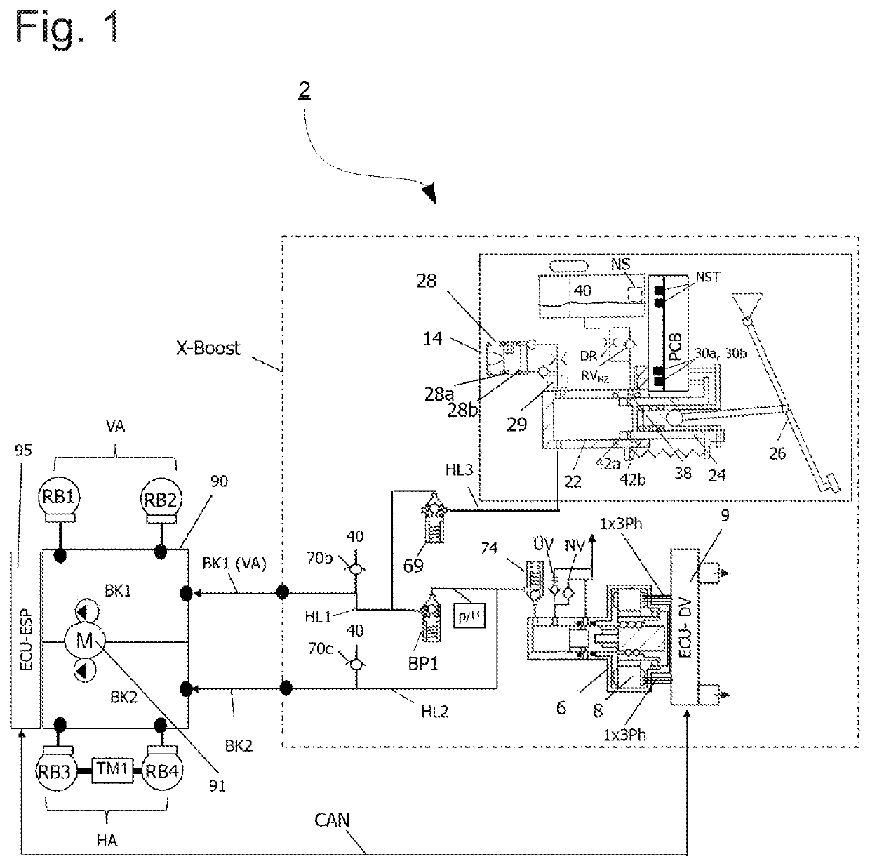
[0107]FIG. 1 shows a schematic circuit diagram of a brake system 2 comprising a first module (referred to as X-Boost) and a second module. The first module—the X-Boost—has a first pressure supply unit 6 with an electromotive drive 8 as well as a second pressure supply unit 14 with a main brake cylinder 22 and an actuating element 26 with a brake pedal. Furthermore, a valve device with various solenoid and check valves is provided.

[0108]The second module comprises an electrically driven motor-pump unit 90 (also referred to as an ESP unit) having a pump with an electromotive drive 91—also referred to as a third pressure supply unit. The motor-pump unit 90 may be any ESP unit. A suitable ESP unit is described in detail in DE 10 2014 205 645 A1. Alternatively, a standard ABS unit without ESP function can be used as the second module.

[0109]The two modules (X-boost and ESP unit) are set up to supply pressure medium to two brake circuits BK1 and BK2, wherein the modules are preferably conn...


PUM


Abstract

A brake system may include a first pressure supply unit having an electromotive drive and arranged to supply pressure medium to first and second brake circuits; a motor-pump unit to supply pressure medium to at least one of the brake circuits; a second pressure supply unit, connected to the motor-pump unit via first and second hydraulic lines and arranged to supply pressure medium to at least one of the brake circuits; and a valve unit. The second pressure supply unit may be connected via a third hydraulic line to at least one of the brake circuits. The valve unit may include at least one feed valve via which the third hydraulic line may be at least partially reversibly shut off. An isolating valve may be disposed in at least one of the hydraulic lines to at least partially reversibly shut off the at least one hydraulic line.

Description

CROSS-REFERENCE TO RELATED APPLICATIONS[0001]This application is a Section 371 of International Application No. PCT / EP2020 / 051995, filed Jan. 28, 2020, which was published in the German language on Nov. 12, 2020 under International Publication No. WO 2020 / 224814 A1, which claims priority under 35 U.S.C. § 119(b) to International Patent Application No. PCT / EP2019 / 061365, filed May 3, 2019, and International Patent Application No. PCT / EP2019 / 061371, filed May 3, 2019, the disclosures of which are incorporated herein by reference.BACKGROUND OF THE INVENTION[0002]The trend towards vehicles with autonomous driving places high demands on the brake system in terms of fault tolerance on the one hand and redundant functions, e.g. for brake pressure generation, power supply and computer functions on the other.[0003]So-called one-box and two-box systems are usually favored. The latter consist of an electric brake booster (BKV), a so-called e-booster, and an ESP system (electronic stability con...

Claims


Application Information

Patent Timeline
IPC IPC(8): B60T13/68B60T8/40B60T15/02B60T13/14B60T17/22B60T8/94B60T13/58
CPCB60T13/686B60T8/4081B60T15/028B60T13/142B60T17/22B60T2270/60B60T13/586B60T2270/402B60T2270/406B60T2270/306B60T2270/403B60T8/94B60T8/409B60T8/5012
Inventor LEIBER, HEINZLEIBER, THOMAS
Owner IPGATE
Why Eureka
Try Eureka