Capacitor resonator modulator

Pending Publication Date: 2022-08-04
UNIV OF SOUTHAMPTON
View PDF0 Cites 0 Cited by
  • Summary
  • Abstract
  • Description
  • Claims
  • Application Information

AI Technical Summary

Benefits of technology

The patent text discusses a new method for making a modulator device that includes a polycrystalline material, which helps prevent crystallisation steps and makes the device cheaper and easier to make. The method also includes depositing or growing insulating material onto the inner wall to control the thickness and angle of the insulating region, which improves the efficiency of the modulator. Additionally, the inner conductive region is not etched to keep a thicker polycrystalline inner disk in the centre, which reduces resistance to injected carriers and improves the optical quality of the device.

Problems solved by technology

The fact that the finished modulator product contains a polycrystalline material is important and goes against the teaching of the prior art (e.g. Shin et al.).
This is contrary to the teaching in the prior art.

Method used


Image

  • Capacitor resonator modulator
  • Capacitor resonator modulator
  • Capacitor resonator modulator

Examples


Embodiment Construction

[0091]Aspects and embodiments of the present invention will now be discussed with reference to the accompanying figures. Further aspects and embodiments will be apparent to those skilled in the art. All documents mentioned in this text are incorporated herein by reference.

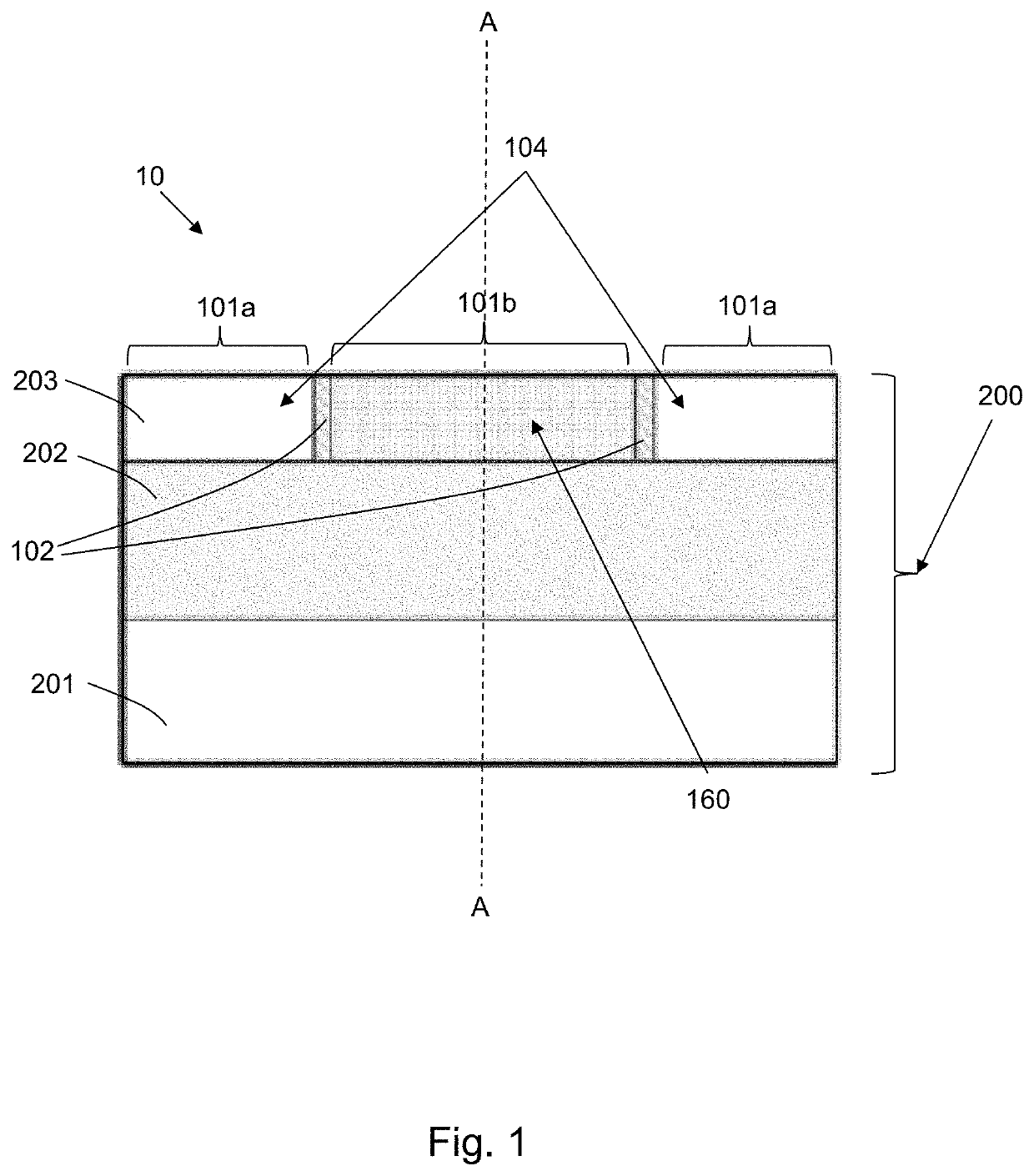
[0092]FIG. 1 is a cross-sectional view of a resonator modulator (10) for modulating light in a photonic circuit in accordance with one embodiment. The modulator (10) comprises: a capacitor formed of a ring-shaped insulating region (102) sandwiched between an outer conductive region (101a) and an inner conductive region (101b). At least one of the outer (101a) conductive regions or the inner conductive regions (101b) is a polycrystalline semiconductor material.

[0093]The resonator modulator (10) comprises a body (200) comprising a semiconductor layer (203), an underlaying layer (202), and a semiconductor substrate layer (201). A bottom surface of the modulator (10) is the surface that is closest to the semiconductor ...


PUM


Abstract

A resonator modulator for modulating light in a photonic circuit, the modulator comprising: a capacitor formed of a ring-shaped insulating region sandwiched between an outer conductive region and an inner conductive region, wherein at least one of the outer conductive regions or the inner conductive regions is a polycrystalline semiconductor material.

Description

CROSS-REFERENCES TO RELATED APPLICATIONS[0001]This application claims priority to GB 2101277.8 (the “277.8 Application”), filed Jan. 29, 2021, by Weiwei Zhang et al. entitled, “A Capacitor Resonator Modulator,” the disclosure of which is incorporated herein by reference in its entirety for all purposes.FIELD OF THE INVENTION[0002]The present invention relates to a capacitor resonator modulator and a method of fabricating a capacitor resonator modulator.BACKGROUND OF THE INVENTION[0003]Modulating light efficiently for data communication is a key function in integrated photonics.[0004]Ring-shaped (or simply “ring”) resonator modulators are often used due the fact that light can be delayed or trapped for a certain time within a ring shape. They are used to reduce the electrically loaded capacitances from photonics structures composed of PN junctions or capacitors, due the fact that light can be delayed or trapped for a certain time in the ring. Ring resonators therefore advantageously ...

Claims


Application Information

Patent Timeline
IPC IPC(8): G02F1/025
CPCG02F1/025G02F2202/06G02F2201/063G02F2203/15G02F1/2257
Inventor ZHANG, WEIWEIREED, GRAHAMTHOMSON, DAVIDEBERT, MARTINSAITO, SHINICHI
Owner UNIV OF SOUTHAMPTON
Why Eureka
Try Eureka