
Verification of computer vision models

a computer vision and model technology, applied in the field of verification of computer vision models, can solve the problems of directing additional glare towards the windscreen how to perform verification, and which attributes should be verified, and achieve the effect of reducing the number of eyes of the ego vehicl

Pending Publication Date: 2022-07-21
ROBERT BOSCH GMBH
View PDF0 Cites 0 Cited by
  • Summary
  • Abstract
  • Description
  • Claims
  • Application Information

AI Technical Summary

Benefits of technology

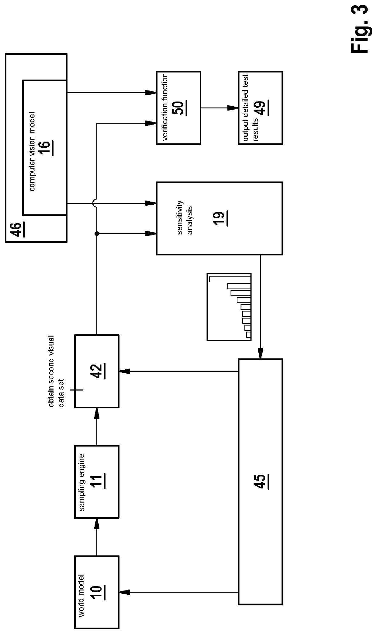
The patent text describes a method for reducing the computational load and complexity of verifying a computer function by focusing on visual parameters that are more sensitive to the computer vision function. This allows for faster automated verification while ensuring that sensitive aspects of the computer vision model have been adequately verified. The method also suggests using a global sensitivity analysis to reduce the number of parameters to be verified, which speeds up the verification process. Additionally, the method reduces the size of the parameter space and enables a faster and more energy efficient training and / or verification process by eliminating redundant parameters. Groundtruth data is used to assess the correctness of the computer vision function and calculate a performance measure.

Problems solved by technology

In automotive computer vision systems, computer vision often has to deal with open context, despite remaining safety-critical.
Verification of computer vision functions using deep neural networks is a major challenge, and crucial for using these functions in safety-critical systems such as autonomous vehicles and robots.
How to perform verification, and which attributes should be verified, is a difficult question.
Further difficult questions concern the test strategy—how test results should be composed into an overall verification plan and organised, for example, in goal-structured notation (GSN).
As one example, a wet road surface with the sun directly ahead of the ego-vehicle might result in additional glare being directed towards the windscreen of the ego vehicle.
This condition could affect how accurately a computer vision model could classify road signs located forward of the ego vehicle, owing to increased glare.
Therefore, the performance of the computer vision model would show a higher result variance.

Method used


Image

  • Verification of computer vision models
  • Verification of computer vision models
  • Verification of computer vision models

Examples


Embodiment Construction

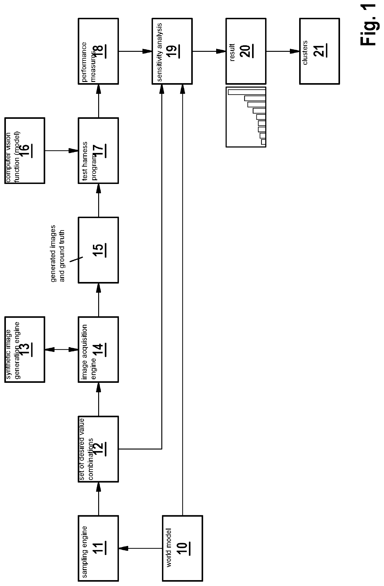
[0052]One or more visual parameters define a visual state of a scene because it or they contain information about the contents of the observed scene and / or represent boundary conditions for capturing and / or generating the observed scene. A typical scene is characterized by a large number of visual parameters, some of which are continuous variables. Therefore, the search space for computing functions over the total number of visual parameters characterizing a typical scene is onerous.

[0053]The visual parameters can be for example: camera properties (e.g. spatial- and temporal-sampling, distortion, aberration, color depth, saturation, noise etc.), LIDAR or RADAR properties (e.g., absorption or reflectivity of surfaces, etc.), light conditions in the scene (light bounces, reflections, light sources, fog and light scattering, overall illumination, etc.), materials and textures, objects and their position, size, and rotation, geometry (of objects and environment), parameters defining the...


PUM


Abstract

Reducing the number of parameters in a visual parameter set based on a sensitivity analysis of how a given visual parameter affects the performance of a computer vision model to provide a verification parameter set having a reduced size.

Description

CROSS REFERENCE[0001]The present application claims the benefit under 35 U.S.C. § 119 of German Patent Application No. DE 102021200345.1 filed on Jan. 15, 2021, which is expressly incorporated herein by reference in its entirety.FIELD[0002]The present invention relates to computer-implemented method for verifying a computer vision model, and an associated apparatus, computer program, and computer readable medium.BACKGROUND INFORMATION[0003]Computer vision concerns how computers can automatically gain high-level understanding from digital images or videos. Computer vision systems are finding increasing application to the automotive or robotic vehicle field. Computer vision can process inputs from any interaction between at least one detector and the environment of that detector. The environment may be perceived by the at least one detector as a scene or a succession of scenes.[0004]In particular, interaction may result from at least one camera, a multi-camera system, a RADAR system o...

Claims


Application Information

Patent Timeline
Patent Type & Authority Applications(United States)
IPC IPC(8): G06V10/776G06V10/764G06V10/762
CPCG06V10/776G06V10/762G06V10/764G06N20/00G06N3/045G06F18/214G06V10/774G06V20/58
Inventor GLADISCH, CHRISTOPHHEINZEMANN, CHRISTIANWOEHRLE, MATTHIAS
Owner ROBERT BOSCH GMBH
Learn More