Eureka AIR delivers breakthrough ideas for toughest innovation challenges, trusted by R&D personnel around the world.

Flexible electroluminescent devices

a flexible, electroluminescent technology, applied in the direction of solid-state devices, semiconductor devices, organic semiconductor devices, etc., can solve the problems of complex and/or expensive encapsulation processes, difficult manufacturing and encapsulation of fel devices at low cost,

Pending Publication Date: 2022-06-30
NANOSYS INC
View PDF0 Cites 0 Cited by
  • Summary
  • Abstract
  • Description
  • Claims
  • Application Information

AI Technical Summary

Benefits of technology

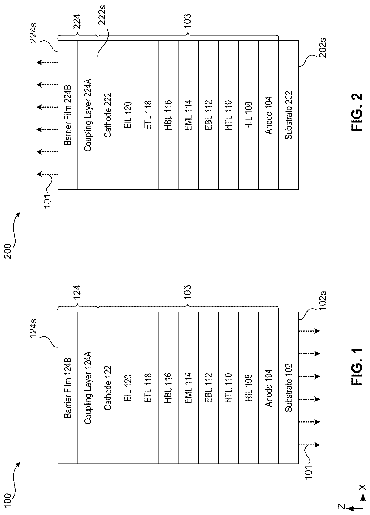
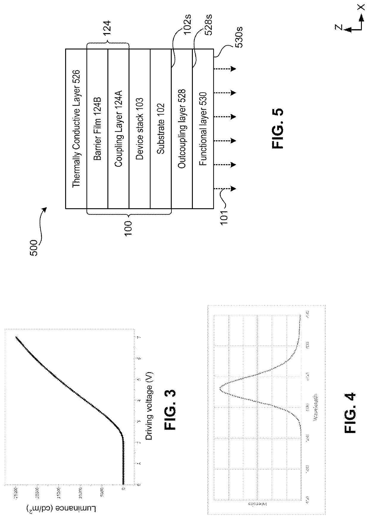
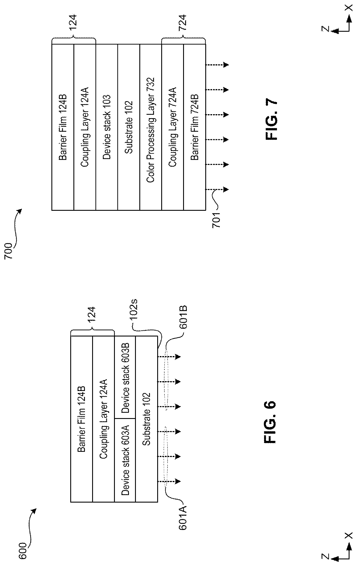
The present disclosure describes inexpensive, high brightness light producing FEL devices with nanostructure emission layers that are effective against moisture, oxygen, and contaminants. The devices can be configured to emit light with primary emission peak wavelengths in the visible and IR spectra, and can be stretchable and conformal to non-uniform surfaces for photomedical applications. The devices have relatively high WVTR and can be encapsulated with inexpensive barrier materials, reducing manufacturing costs and facilitating mass production. Additionally, the devices can have outcoupling layers to extract light from the flexible substrate and eliminate air gaps for conformal placement on surfaces.

Problems solved by technology

However, one of the challenges is producing flexile EL (FEL) devices that emit light with high brightness (also referred to as luminance) (e.g., brightness greater than about 20,000 candelas per square meter (cd / m2)) at low driving voltages (e.g., voltages less than about 8 volts(V)) for effective penetration of the light into the human skin for photomedical applications, for example.
Another challenge is encapsulating the FEL devices to provide them with mechanical and / or environmental protection (e.g., protection from moisture and / or contaminants) in order to achieve similar or longer operational lifetime and efficiency compared to the non-flexible EL devices.
Also, manufacturing and encapsulating of FEL devices at low costs with simple processing technologies for ease of mass production is challenging.
The Cd-free FEL devices can be suitable for applications in photomedicine, for example, as the intrinsic toxic properties of cadmium can be detrimental to human health.
As such, the FEL devices does not have to be encapsulated with barrier materials having very low water vapor transmission rate (WVTR) (e.g., less than 10−5 g / m2-day), which can require complicated and / or expensive encapsulation processes.

Method used


Image

  • Flexible electroluminescent devices
  • Flexible electroluminescent devices
  • Flexible electroluminescent devices

Examples


Embodiment Construction

[0026]Although specific configurations and arrangements may be discussed, it should be understood that this is done for illustrative purposes only. A person skilled in the pertinent art will recognize that other configurations and arrangements can be used without departing from the spirit and scope of the present invention. It will be apparent to a person skilled in the pertinent art that this invention can also be employed in a variety of other applications beyond those specifically mentioned herein. It should be appreciated that the particular implementations shown and described herein are examples and are not intended to otherwise limit the scope of the application in any way.

[0027]It is noted that references in the specification to “one embodiment,”“an embodiment,”“an example embodiment,” etc., indicate that the embodiment described may include a particular feature, structure, or characteristic, but every embodiment may not necessarily include the particular feature, structure, ...


PUM


Abstract

Embodiments of a flexible electroluminescent (FEE) device are described. An FEE device includes a device stack with a quantum dot (QD) film configured to generate a first light having a first peak wavelength and a flexible substrate configured to support the device stack and emit a first portion of the first light. The FEE device further includes an encapsulation layer disposed on the device stack and an outcoupling layer disposed on the flexible substrate. The encapsulation layer can be configured to provide mechanical and environmental protection to the FEE device from moisture or oxygen. The outcoupling layer can be configured to prevent total internal reflection of a second portion of the first light within the flexible substrate and extract the second portion from the flexible substrate. The outcoupling layer can be further configured to eliminate air gaps at an interface between the outcoupling layer and a surface to be illuminated by the extracted second portion in response to the FEE device being substantially conformally placed on the surface.

Description

BACKGROUND OF THE INVENTIONField[0001]The present invention relates to electroluminescent devices (e.g., light emitting diodes (LEDs)) having luminescent nanostructure (e.g., quantum dot (QD)) based emission layers on flexible substrates.Background[0002]Electroluminescent (EL) devices are used as light sources in displays (e.g., phones, tablets, monitors, televisions, or digital billboards) and medical applications (e.g., photomedicine). With the increase in demand for portable and wearable devices, EL devices (e.g., LEDs and organic LEDs (OLEDs)) have been made on lightweight and flexible substrates, which can be curved without causing structural and functional damage to the EL devices.[0003]However, one of the challenges is producing flexile EL (FEL) devices that emit light with high brightness (also referred to as luminance) (e.g., brightness greater than about 20,000 candelas per square meter (cd / m2)) at low driving voltages (e.g., voltages less than about 8 volts(V)) for effect...

Claims


Application Information

Patent Timeline
IPC IPC(8): H01L51/52H01L51/56H01L51/50
CPCH01L51/5275H01L51/56H01L51/0097H01L51/529H01L2251/5338H01L51/502H10K77/111H10K50/13H10K50/115H10K2102/311H10K59/875H10K59/873H10K59/8794H10K50/858H10K71/00H10K50/87H10K50/844
Inventor MA, RUIQINGHARTLOVE, JASONHOTZ, CHARLES
Owner NANOSYS INC
Why Eureka
Eureka Blog
Learn More