
Acoustofluidic device

Pending Publication Date: 2022-06-23
UNIV COLLEGE CARDIFF CONSULTANTS LTD
View PDF0 Cites 2 Cited by
  • Summary
  • Abstract
  • Description
  • Claims
  • Application Information

AI Technical Summary

Benefits of technology

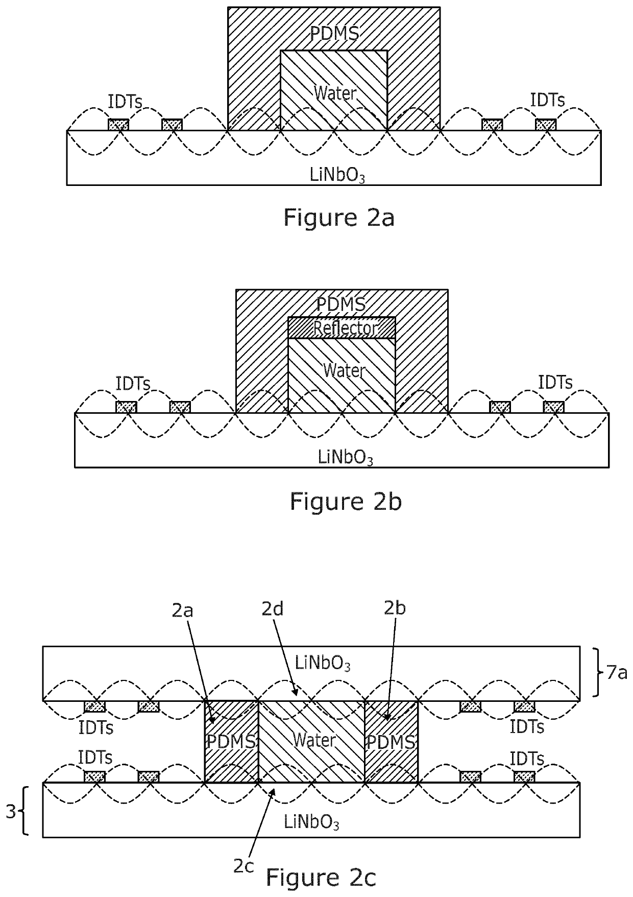
[0096]The four different model configurations considered in this study are shown in FIG. 2(a-d). The typical SSAW transducer made by patterning a pair of interdigital electrodes on LiNbO3 bonded with a PDMS channel is given in FIG. 2(a). Operating under the same RF signal, two SAWs generated by the IDTs counter-propagate to produce a standing SAW (SSAW) within the channel. Stable acoustic pressure gradients are formed in the water flowing in the channel which exerts acoustic radiation force and streaming drag force on the particles inside the channel. We call this typical acoustofluidic structure as SAW-PDMS. FIG. 2(b) shows the model of the novel structure of an acoustofluidic chip29, 30 for high throughput CTC separation, which employs a glass slide as an acoustic reflector attached on the top of the channel, namely hybrid PDMS-glass resonator (we call it SAW-Glass). The reflector prevents the acoustic energy loss caused by the PDMS absorption on the top.
[0097]To further increase the acoustic energy pressure in the channel for enhanced manipulation of particles, we developed two new models of acoustofluidic structures as shown in FIG. 2(c) and FIG. 2(d). In FIG. 2(c), the top wall of the PDMS channel is repl

Problems solved by technology

Due to the attenuation of the acoustically soft channel material, acoustic waves propagating inside the channel are absorbed into the channel material resulting in acoustic energy loss.
Further, the height of channel further limits the size of samples that can be processed.
Increasing the input power of the SAW device may be able to compensate the loss but the induced Joule

Method used


Image

  • Acoustofluidic device
  • Acoustofluidic device
  • Acoustofluidic device

Examples


Example

[0065]In a first embodiment, as shown in FIG. 2c, the acoustic wave source [7] is provided as a further SSAW transducer [7a] thus forming two SSAW transducers (i.e. as the channel floor [3] and roof [7a]), termed SAW-SAW. Respectively, each SSAW transducer [3],[7a] can be independently controlled such that the acoustic waves generated by same can be carefully controlled to manipulate particle flow in both vertical and lateral planes thus providing for an extra level of particle flow separation. Preferably, to achieve higher resolution of particle flow and thus separation, it has been found that fine tuning the phase difference between each respective SSAW transducer one can generate symmetrical pressure anti-nodes to form good particle trajectories.

Example

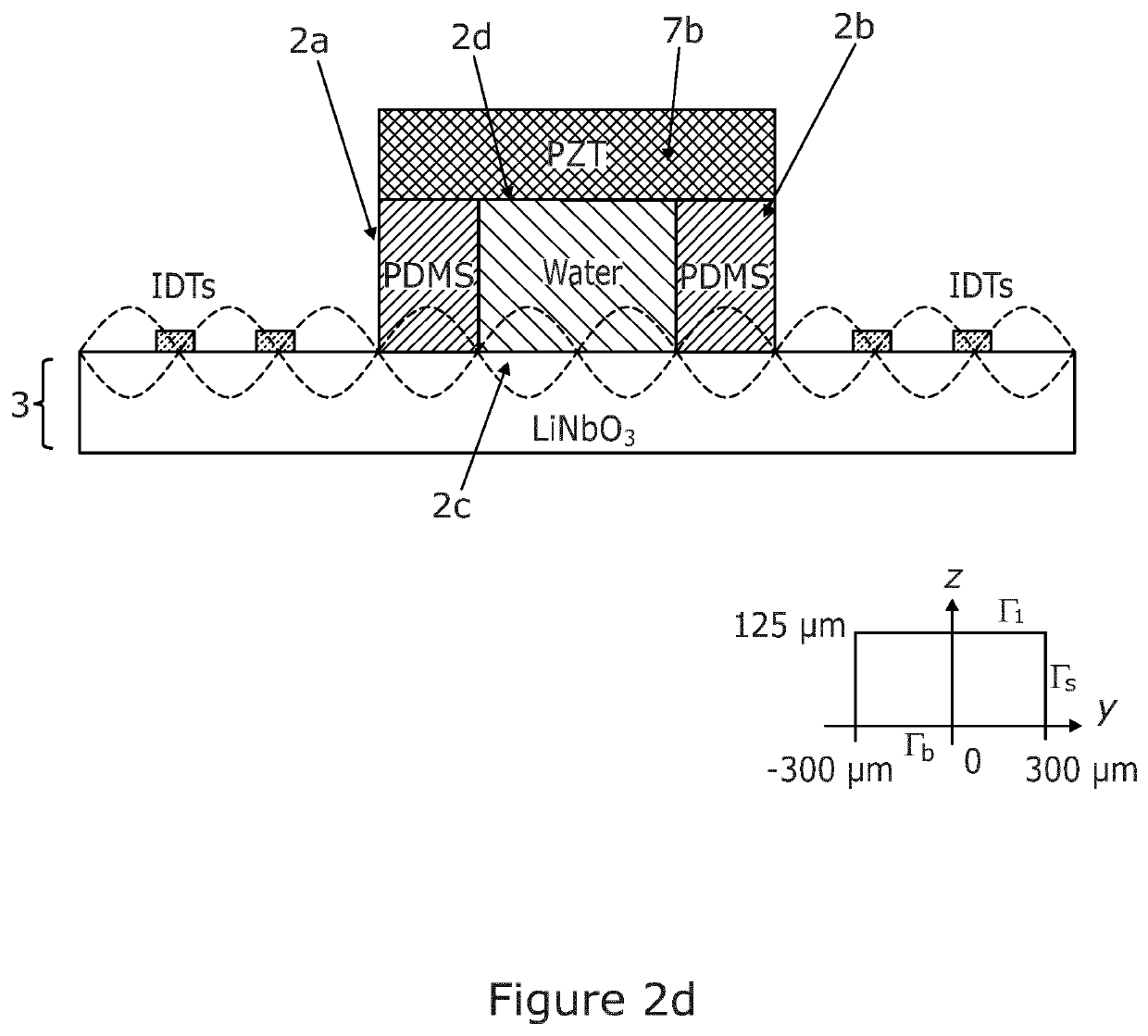
[0066]Alternatively, in a second embodiment as shown in FIG. 2d, the acoustic wave source is provided as a bulk acoustic piezoelectric transducer [7b] producing bulk acoustic waves (BAWs). In this arrangement (called BAW-SAW) the channel floor [2c] is provided by the SSAW transducer of the substrate and the roof [2d] is defined by a bulk acoustic (BAW) piezoelectric transducer [7b]. It has been found that in this particular arrangement one can also achieve stronger pressure gradients in the channel of several orders of magnitude greater than conventional arrangements known in the art. RF signals from a source (not shown) drive both the BAW [7b] and SSAW [3] transducers to produce a combined acoustic energy in the channel [2]. Changing the input voltage of the BAW [7b] and SSAW [3] transducers can vary the integrated acoustic field.

[0067]Therefore, as will be appreciated, in all embodiments the SSAW transducers [3] and / or acoustic wave source [7a, 7b] can be operated in phase with ea...


PUM

PropertyMeasurementUnit
Widthaaaaaaaaaa
Widthaaaaaaaaaa
Widthaaaaaaaaaa

Abstract

The invention concerns a novel acoustofluidic device to separate acoustically active particles from fluids comprising a novel device arrangement for improved acoustic pressure and particle velocity; and a method of separating particles from a fluid comprising use of same.

Description

FIELD OF THE INVENTION[0001]The invention concerns a novel acoustofluidic device to separate acoustically active particles from fluids comprising a novel device arrangement for improved acoustic pressure and particle velocity; and a method of separating particles from a fluid comprising use of same.BACKGROUND OF THE INVENTION[0002]Acoustophoresis is the separation of particles using acoustic wave. It has been known that acoustic wave can exert forces on particles in the acoustic field which can be determined by the particles' volume, density and compressibility. The pressure profile in a standing acoustic wave contains areas of net zero pressure at the nodes and of maximum at the anti-nodes. Depending on the acoustic contract factor of the particles, they will be trapped at the pressure nodes or pressure anti-nodes of the standing acoustic wave.[0003]A wide range of acoustofluidic devices integrating a channel and acoustic transducer have been developed for applications in biochemis...

Claims


Application Information

Patent Timeline
IPC IPC(8): B01L3/00B01D21/28B06B1/02B06B1/06
CPCB01L3/50273B01D21/283B06B1/0238B06B1/0688B06B2201/77B01L2300/0861B01L2400/0436B01L2400/0439B01L2200/0652B06B1/0644G10K11/36
Inventor YANG, XIN
Owner UNIV COLLEGE CARDIFF CONSULTANTS LTD
Learn More