Laser beam wavefront correction with adaptive optics and mid-field monitoring

a wavefront correction and adaptive optics technology, applied in the field of laser beam wavefront correction, can solve the problem of wavefront deformation problem and the shift in the location and size of the laser beam waist, and achieve the effect of reducing cost and complexity

Pending Publication Date: 2022-05-26
COHERENT LASERSYST
View PDF0 Cites 1 Cited by
  • Summary
  • Abstract
  • Description
  • Claims
  • Application Information

AI Technical Summary

Benefits of technology

[0008]We have further found that the wavefront correction, required to stabilize the waist location based on mid-field monitoring, may be performed with relatively simple adaptive optics, for example one or more deformable cylindrical mirrors each having as little as three actuators. This represents a significant reduction in cost and complexity, as compared to systems relying on the deformable mirrors commercially available today.

Problems solved by technology

We have realized that in certain common types of laser systems, the dominant wavefront deformation problem is a shift in the location and size of a laser beam waist.

Method used


Image

  • Laser beam wavefront correction with adaptive optics and mid-field monitoring
  • Laser beam wavefront correction with adaptive optics and mid-field monitoring
  • Laser beam wavefront correction with adaptive optics and mid-field monitoring

Examples


Embodiment Construction

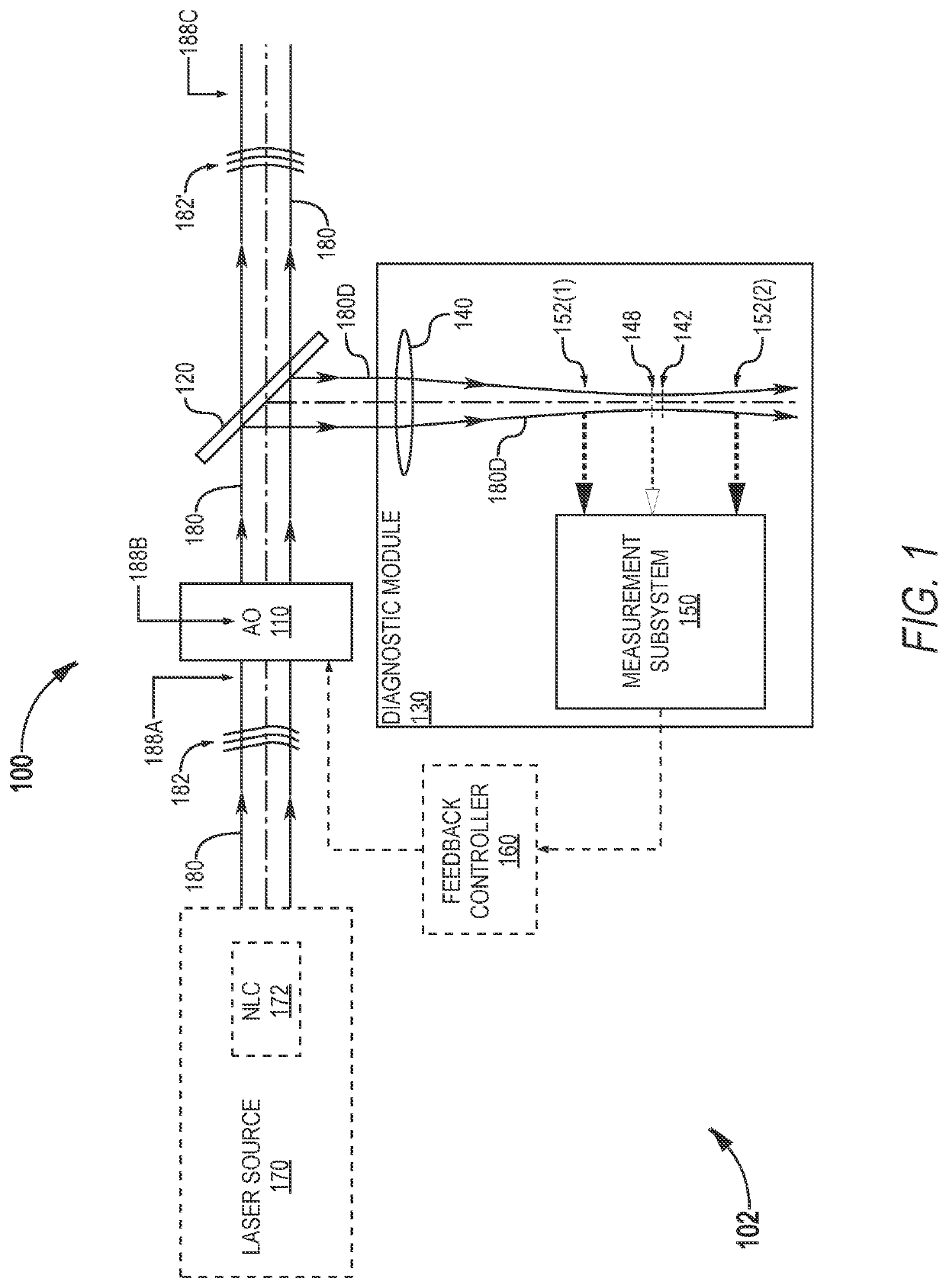
[0026]Referring now to the drawings, wherein like components are designated by like numerals, FIG. 1 illustrates one system 100 for correcting the wavefront 182 of a laser beam 180. System 100 system utilizes beam size measurement in the mid-field of laser beam 180. FIG. 1 shows system 100 in an example scenario where system 100 is incorporated into a laser apparatus 102.

[0027]Laser apparatus 102 includes system 100, and a laser source 170 that generates laser beam 180. Laser source 170 may include one or more elements that cause deformation of wavefront 182. Herein, wavefront deformation refers to an unwanted wavefront change as opposed to, e.g., the intended wavefront change imparted by a lens. For example, laser source 170 may include a nonlinear crystal (NLC) 172 that generates laser beam 180 through frequency conversion but, undesirably, also deforms wavefront 182. In one implementation, laser beam 180 is a high-power ultraviolet (UV) laser beam that causes nonlinear crystal 17...


PUM


Abstract

A system for correcting the wavefront of a laser beam includes a beamsplitter for splitting off a fraction of the laser beam to be used as a diagnostic beam, a focusing element for bringing the diagnostic beam to a focus, a measurement subsystem for measuring sizes of the diagnostic beam at upstream and / or downstream locations with respect to a nominal location of the focus, and at least one adaptive optic, located upstream from the beamsplitter, for correcting the wavefront of the laser beam at least partly based on the measured sizes of the diagnostic beam at the upstream and / or downstream locations. The upstream and downstream locations correspond to mid-field locations in the laser beam as imaged by the focusing element. The system takes advantage of the sensitivity of the laser beam size to a waist location shift being greatest at one Rayleigh length from the nominal waist location.

Description

TECHNICAL FIELD OF THE INVENTION[0001]The present invention relates in general to laser beam wavefront correction, in particular to techniques for stabilizing size and divergence properties of laser beams using adaptive optics.DISCUSSION OF BACKGROUND ART[0002]The beam quality of a laser beam characterizes its focusability. The wavefronts of a high-quality laser beam have smooth and simple shapes. A high-quality laser beam can be focused more tightly than a low-quality laser beam. Different measures of beam quality are used in the art. One measure is the beam parameter product (BPP), defined as the product of (i) the beam radius at the beam waist and (ii) the far-field beam divergence angle. The highest possible beam quality is achieved for a diffraction-limited Gaussian beam. Thus, another measure of beam quality is the M2 factor, defined as the ratio of (i) the BPP for the laser beam under consideration to (ii) the BPP of a diffraction-limited Gaussian beam of the same wavelength....

Claims


Application Information

Patent Timeline
Patent Type & Authority Applications(United States)
IPC IPC(8): G02B26/08H01S3/08G02B26/06H01S3/00
CPCG02B26/0833H01S3/005G02B26/06H01S3/08059G02B27/108G02B26/0825G02B27/0068G01J1/4257H01S3/0014H01S3/0092H01S3/0071G01J1/0448G01J1/0411G01J1/0414
Inventor VON ELM, RÜDIGER
Owner COHERENT LASERSYST
Why Eureka
Try Eureka