
Method for producing an elastic and flexible fiber with optical, electrical or microfluidic functionality

Pending Publication Date: 2022-05-19
DRESDEN UNIVERSITY OF TECHNOLOGY
View PDF0 Cites 0 Cited by
  • Summary
  • Abstract
  • Description
  • Claims
  • Application Information

AI Technical Summary

Benefits of technology

This patent describes a method for making flexible fibers with specific shapes using a single extrusion process. These fibers can be used to create soft robots that can adapt to their environment. The fibers can also be used for fluidic connections, pressure actuators, and electronic interconnects. This method is different from previous methods and allows for the production of elastic and flexible fibers that were previously difficult to make.

Problems solved by technology

Elastomers have been employed to produce fibers, but no guidance is presented on obtaining non-circular cross-sectional geometries.
In particular, methods have not been described in the art for utilizing existing DIW devices with standard nozzles of circular cross-section to develop fibers of noncircular cross-sectional geometries, especially fibers with an elongated indentation along a length of the fiber (groove).

Method used


Image

  • Method for producing an elastic and flexible fiber with optical, electrical or microfluidic functionality
  • Method for producing an elastic and flexible fiber with optical, electrical or microfluidic functionality
  • Method for producing an elastic and flexible fiber with optical, electrical or microfluidic functionality

Examples


example 1

d Velocity Determination

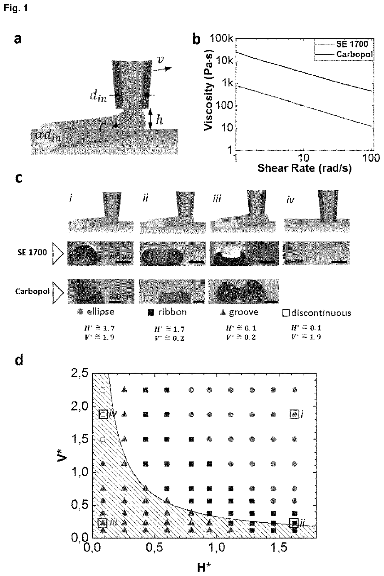
[0151]In standard DIW operations, filaments have close to circular cross sections with diameter αdin. Here din is the inner diameter of the nozzle and α is the die-swelling factor, which describes the post-extrusion expansion of the ink [16]. Stable printing is achieved by setting the translational speed of the print head v to be close to the extrusion speed C, with which ink leaves the nozzle. At the same time, the height of the nozzle above the substrate h is kept similar to αdin (FIG. 1a). Following Yuk and Zhao, we introduce the dimensionless nozzle speed V*≡v / c and height H*≡h / αdin and point out that for conventional DIW with circular cross-section filaments, both parameters are adjusted to be close to unity [15]. The extrusion speed C may depend on the ink, nozzle and applied pressure. For inks that age, C can change over time. Values for C and α can be determined experimentally by printing simple test structures (FIG. 7). In some embodiments, V* and H*...

example 2

usion Modification of the Filament Cross Section

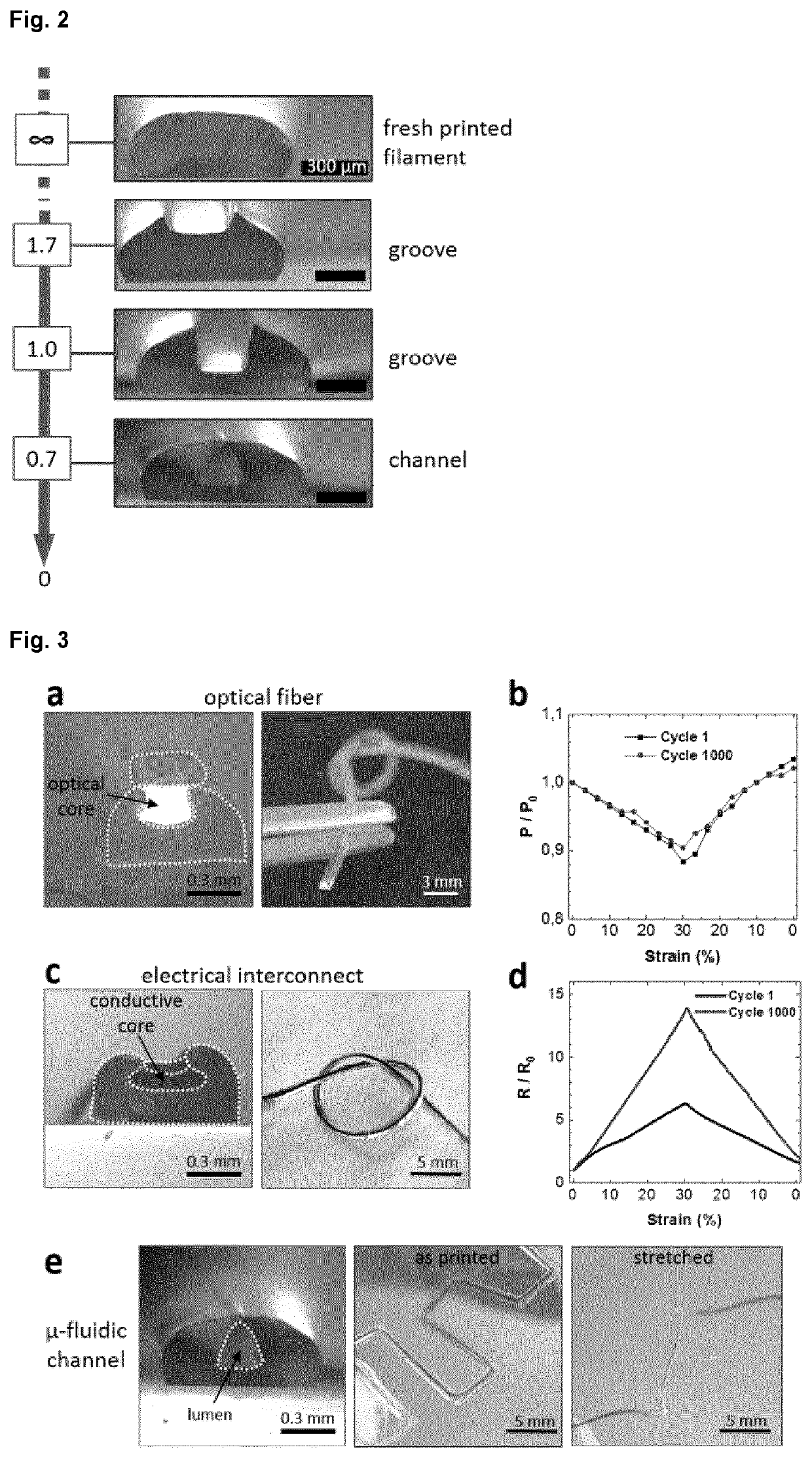
[0156]Post-extrusion modification of the filament cross section is demonstrated below. To do this, we use the nozzle as a stylus by setting to zero (no ink leaves the nozzle). Passing the stylus over a freshly printed (not yet polymerized) ribbon / ellipse filament of SE1700 silicone can create a groove in it (FIG. 2). Interestingly, we observed that engraving deep grooves causes collapse of their walls leaving behind a lumen. The lumen persists even after thermal polymerization of the ink.

Example 3: Functional Core-Shell Fibers

[0157]Next, we combine ribbon and groove filaments to form functional core-shell fibers (FIG. 3). As illustrated in FIG. 3(a), grove filaments can aid patterning a functional core material by restricting its spreading to the confines of the grove. Combined with a ribbon filament printed on top, the grove filaments serve as cladding protecting the core. In the case of conductive fibers, the cladding functions as el...

example 3

l Interconnects

[0160]Similarly, electrical interconnects can be printed by filling groove filaments with a conductive material. Here we use compacted platinum microparticles as the conductive core while the groove and ribbon filaments act as electrical passivation (FIG. 3c). Elastic interconnects produced in this way display average conductivity of 22±3.5 Scm-1 which is similar to the conductivity observed in other metal microparticle based conductive composites [21].

[0161]Electrical interconnects remain conductive when stretched to at least 30% tensile strain (FIG. 3d). Strain of 30% results in 6.80±1.86-fold increase in resistance, which changes to 14.17±2.02 after 1 000 strain cycles. Finally, we demonstrate that using the printing nozzle as a stylus, freeform microfluidic channels can be produced. Printed channels are observed to be free of obstructions (FIG. 3e) and are able to support laminar flow (FIG. 11). The three types of fiber presented here exhibit nearly linear elastic...


PUM

PropertyMeasurementUnit
Lengthaaaaaaaaaa
Lengthaaaaaaaaaa
Lengthaaaaaaaaaa

Abstract

The invention relates to a method for manufacturing an elastic and flexible fiber with a pre-de-termined non-circular cross-sectional geometry, the method comprising extrusion of an elasto-mer from a nozzle onto a substrate, wherein the pre-determined non-circular cross-sectional geometry of the fiber is determined by the height and velocity of the nozzle relative to the sub-strate. The invention relates to an elastic and flexible fiber produced using the method, wherein the fiber comprises an elongated indentation along a length of the fiber (groove). The invention relates to methods for producing preferably biocompatible microfluidic, electrically conducting or light-guiding fibers using the methods of the invention. The invention further re-lates to elastic and flexible fibers produced by the method.

Description

[0001]The invention relates to the field of preferably mesoscale printing of elastic and flexible fibers using Direct Ink Writing (DIW).[0002]The invention relates to a method for manufacturing an elastic and flexible fiber with a pre-determined non-circular cross-sectional geometry, the method comprising extrusion of an elastomer from a nozzle onto a substrate, wherein the pre-determined non-circular cross-sectional geometry of the fiber is determined by the height and velocity of the nozzle relative to the substrate. The invention relates to the method above and to an elastic and flexible fiber produced using the method, wherein the fiber comprises an elongated indentation along a length of the fiber (groove).[0003]The invention relates to methods for producing preferably biocompatible microfluidic, electrically conducting or light-guiding fibers using the methods of the invention.[0004]The invention further relates to elastic and flexible fibers produced by the method, such as fi...

Claims


Application Information

Patent Timeline
IPC IPC(8): B29C48/05B29C48/02B29C48/00B29C48/12B29C48/25B29C64/209B29C64/106B33Y10/00
CPCB29C48/05B29C48/02B29C48/022B29C48/12B29L2011/0075B29C64/209B29C64/106B33Y10/00B29C48/266
Inventor MINEV, IVANAFANASENKAU, DZMITRYPAK, ANNAATHANASIADIS, MARKOS
Owner DRESDEN UNIVERSITY OF TECHNOLOGY
Learn More