
Clad material for cooler, cooler for heat-generating device, and method of producing cooler for heat-generating device

Inactive Publication Date: 2014-06-12
TOYOTA JIDOSHA KK
View PDF6 Cites 5 Cited by
  • Summary
  • Abstract
  • Description
  • Claims
  • Application Information

AI Technical Summary

Benefits of technology

The invention provides a clad material for a cooler that has excellent formability and can be easily brazed with other parts of the cooler. The clad material also exhibits excellent corrosion resistance, preventing the occurrence of corrosion pitting. The cooler made from this material has improved cooling performance and prevents the occurrence of corrosion pitting even in high velocity cooling water flow. The invention also provides a method for producing the cooler using this clad material.

Problems solved by technology

However, when a cooling water flow is present, the constituent members of the cooler experience a severely corrosive environment, and, in the particular case of a thinned down top sheet, the corrosion penetrates the sheet in the thickness direction from the cooling water passage side and corrosion pitting rapidly occurs.
However, in the case of the materials used for the top sheet in conventional coolers, achieving a balance with the formability makes it difficult to improve the corrosion resistance.
When the brazing filler metal erodes the core material, a portion of this brazing filler metal is consumed and the amount of brazing filler metal furnished to brazing with the bottom sheet and inner fin then becomes inadequate and an adequate joint strength is not obtained.
In addition, since corrosion from the cooling water passage side of the top sheet proceeds preferentially from the brazing filler metal composition, there is a risk that corrosion will proceed rapidly in the depth direction when the core material is eroded by the brazing filler metal.
Moreover, even when, by the addition of, e.g., Zn, to the brazing filler metal, a structure is elaborated that provides the function of a sacrificial anticorrosion layer, a satisfactory anticorrosion effect has not been obtained and obtaining an excellent corrosion resistance has been difficult.
However, even with a clad material with this structure, the brazing filler metal clad on the other side erodes the core material and as a consequence corrosion proceeds rapidly at locations where the corrosion developing in the depth direction from the cooling water passage side reaches the braze erosion regions from the other side; there is then a risk that corrosion pitting will rapidly occur.
Thus, when an O material is used as the top sheet material, an excellent press formability is obtained, but it is difficult to raise the corrosion resistance of the top sheet.
In addition to O materials, a variety of aluminum alloy clad materials are also used as top sheet materials, but all of these are quite susceptible to the occurrence of corrosion pitting for the following reason.
Here, when the weld area is broadened due to an overly large heat input by this laser welding, corrosion easily occurs because this weld area is electrochemically base, causing the occurrence of corrosion pitting.
To avoid this, the amount of heat input must be made as small as possible, but since the surface of the material reflects the laser in the case of aluminum alloys, the material abruptly melts in the initial stage of welding and the amount of heat introduction can easily become overly large.
As a consequence, when an aluminum alloy clad material is used as the top sheet, the rapid occurrence of corrosion pitting is a risk due to corrosion in the depth direction from regions welded by laser welding.

Method used


Image

  • Clad material for cooler, cooler for heat-generating device, and method of producing cooler for heat-generating device
  • Clad material for cooler, cooler for heat-generating device, and method of producing cooler for heat-generating device

Examples


first embodiment

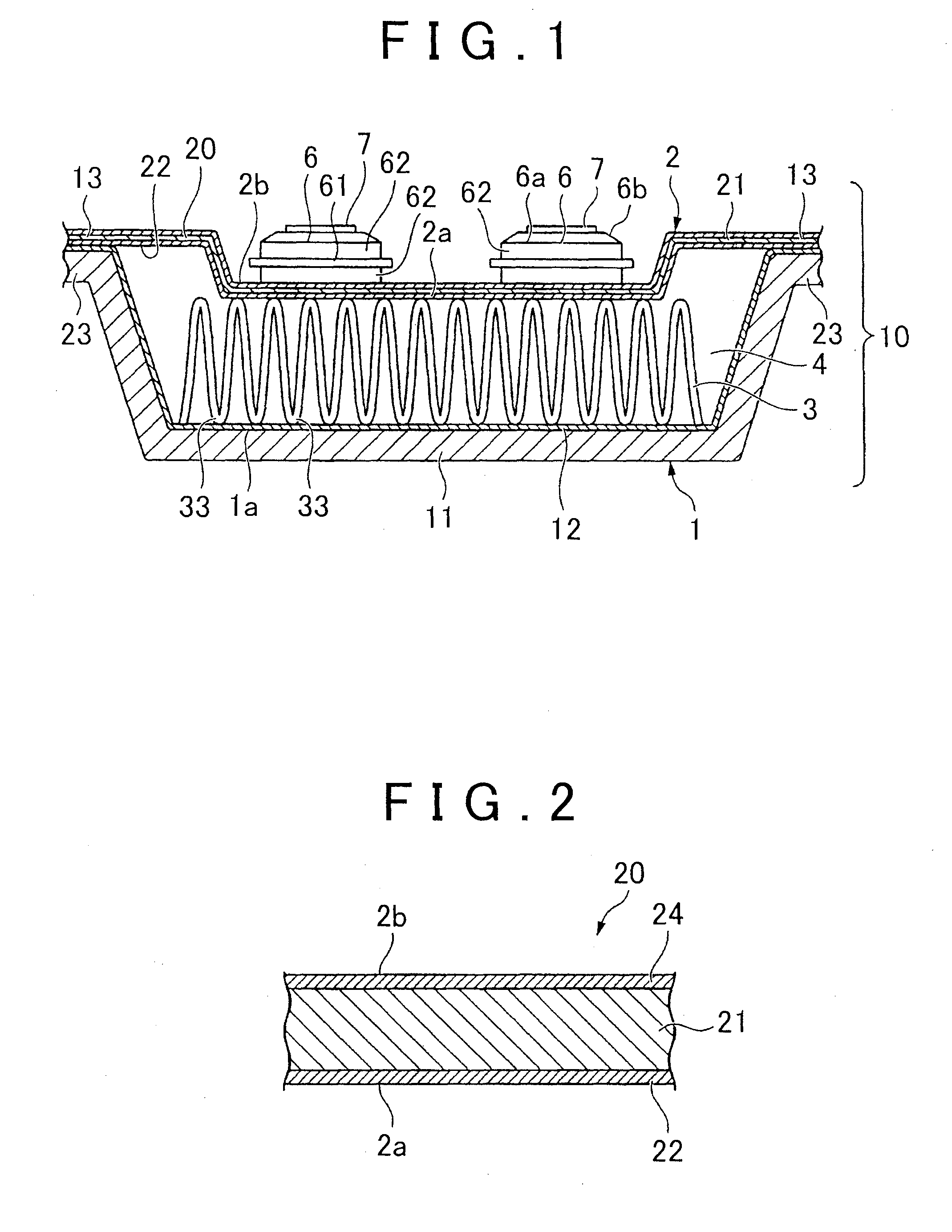
[0038]A first embodiment of a cooler for a heat-generating device, which uses a clad material for a cooler according to the invention, will be described first. FIG. 1 is a schematic cross-sectional diagram that shows the first embodiment of a cooler for a heat-generating device, which uses a clad material for a cooler according to the invention. FIG. 2 is a schematic cross-sectional diagram that shows an example of a clad material for a cooler, which is used as the material of the top sheet in the cooler for a heat-generating device shown in FIG. 1.

[0039]The cooler 10 for a heat-generating device (referred to below simply as a “cooler”), shown in FIG. 1, is constructed by stacking a bottom sheet 1, which has a shape in which a plurality of sections processed to have a trough-shaped cross section are connected in the lateral direction, an inner fin 3, which resides in the trough-shaped section of the bottom sheet 1, and a top sheet 2 in the given sequence and, using the brazing fille...

second embodiment

The Second Embodiment

[0088]A second embodiment of a cooler for a heat-generating device (a cooler for a heat-generating device according to the invention) that uses another example of a clad material for a cooler according to the invention. Those structures in the second embodiment that are similar to those of the previously described first embodiment will not be described in detail again. The cooler for a heat-generating device of the second embodiment is similar to the first embodiment, except that there is a change in the structure of the clad material 20 for a cooler used as the material of the top sheet 2.

[0089]In this embodiment, the clad material for a cooler has a sacrificial material layer in place of the first brazing filler metal layer 22, while its other elements, i.e., the composition of the core material and the brazing filler metal layer (the second brazing filler metal layer 24 in the first embodiment), the finish rolling ratio, and the pre- and post-brazing properti...

examples 1-8

, Comparative Examples 1-5: inner fin C (refer to Table 3)


PUM

PropertyMeasurementUnit
Temperatureaaaaaaaaaa

Abstract

A clad material for a cooler is provided by executing production of a tensile strain of 3 to 10% or rolling at a finish rolling ratio of 10 to 25%, and optionally performing a heat treatment for 1 to 8 hours at a temperature within a range from 150 to 400° C., on a clad raw material having a three layer structure of a core material, a first brazing filler metal layer that covers one side (the surface on the side of a cooling water passage) of this core material, and a second brazing filler metal layer that covers the other side (the surface on the opposite side from the cooling water passage). Specific ranges are prescribed for certain properties before and after brazing.

Description

BACKGROUND OF THE INVENTION[0001]1. Field of the Invention[0002]The invention relates to a clad material for a cooler, used in a cooler that is mounted in an electric automobile or a hybrid automobile, or on any of various electronic device circuits, and cools a heat-generating device such as a semiconductor device. The invention further relates to a cooler for a heat-generating device in which the clad material for a cooler is used, and also relates to a method of producing a cooler for a heat-generating device.[0003]2. Description of Related Art[0004]Coolers that cool heat-generating devices such as semiconductor devices are mounted in electric automobiles or hybrid automobiles, or on various electronic device circuits. A so-called water-cooled cooler is available, in which a top sheet formed of an aluminum alloy sheet to which the cooling target is attached, a bottom sheet of an aluminum alloy sheet, which defines a cooling water passage between the bottom sheet and the top sheet...

Claims


Application Information

Patent Timeline
IPC IPC(8): F28F21/08B23K1/00
CPCC22C9/00C22C9/02C22C9/06C22C21/02C22C21/10F28F21/081F28F21/089H01L21/4878H01L23/473B23K1/0012C22C2204/00H01L2924/0002B23K35/28B23K35/286B32B15/016C22C21/00H01L2924/00F28F21/08H01L23/3735
Inventor KURODA, SHUYOSHINO, MICHIHIDEOHNO, KAZUTAKAFUKAMI, TOMOSUGINO, YUJI
Owner TOYOTA JIDOSHA KK
Learn More