
Method for detecting an internal short circuit in a first electrical energy storage unit of an electrical energy storage device

Active Publication Date: 2019-07-11
ROBERT BOSCH GMBH
View PDF0 Cites 0 Cited by
  • Summary
  • Abstract
  • Description
  • Claims
  • Application Information

AI Technical Summary

Benefits of technology

The patent is about a method to detect short-circuit currents in battery systems. The method uses a Hall-effect current sensor or a shunt current sensor to record the electric current flowing into or out of each battery unit. By analyzing these recorded currents, the method can determine if there is a short-circuit in one of the batteries. This helps to prevent dangerous situations from occurring and ensures the proper operation of the battery system. The method also allows for the determination of the internal resistance ratio of the batteries, which further enhances the accuracy of the short-circuit current detection. This makes the method more reliable and robust in detecting the short-circuit current. The patent describes both the technical effects of the method and a computer program for its implementation.

Problems solved by technology

This causes a decrease in the externally visible internal resistance of the first electrical energy storage unit.
The method is therefore relatively insensitive to an offset current in the current measurement by means of a current sensor.

Method used


Image

  • Method for detecting an internal short circuit in a first electrical energy storage unit of an electrical energy storage device
  • Method for detecting an internal short circuit in a first electrical energy storage unit of an electrical energy storage device
  • Method for detecting an internal short circuit in a first electrical energy storage unit of an electrical energy storage device

Examples


Embodiment Construction

[0026]The same reference numerals refer to the same device components or the same method steps in all figures.

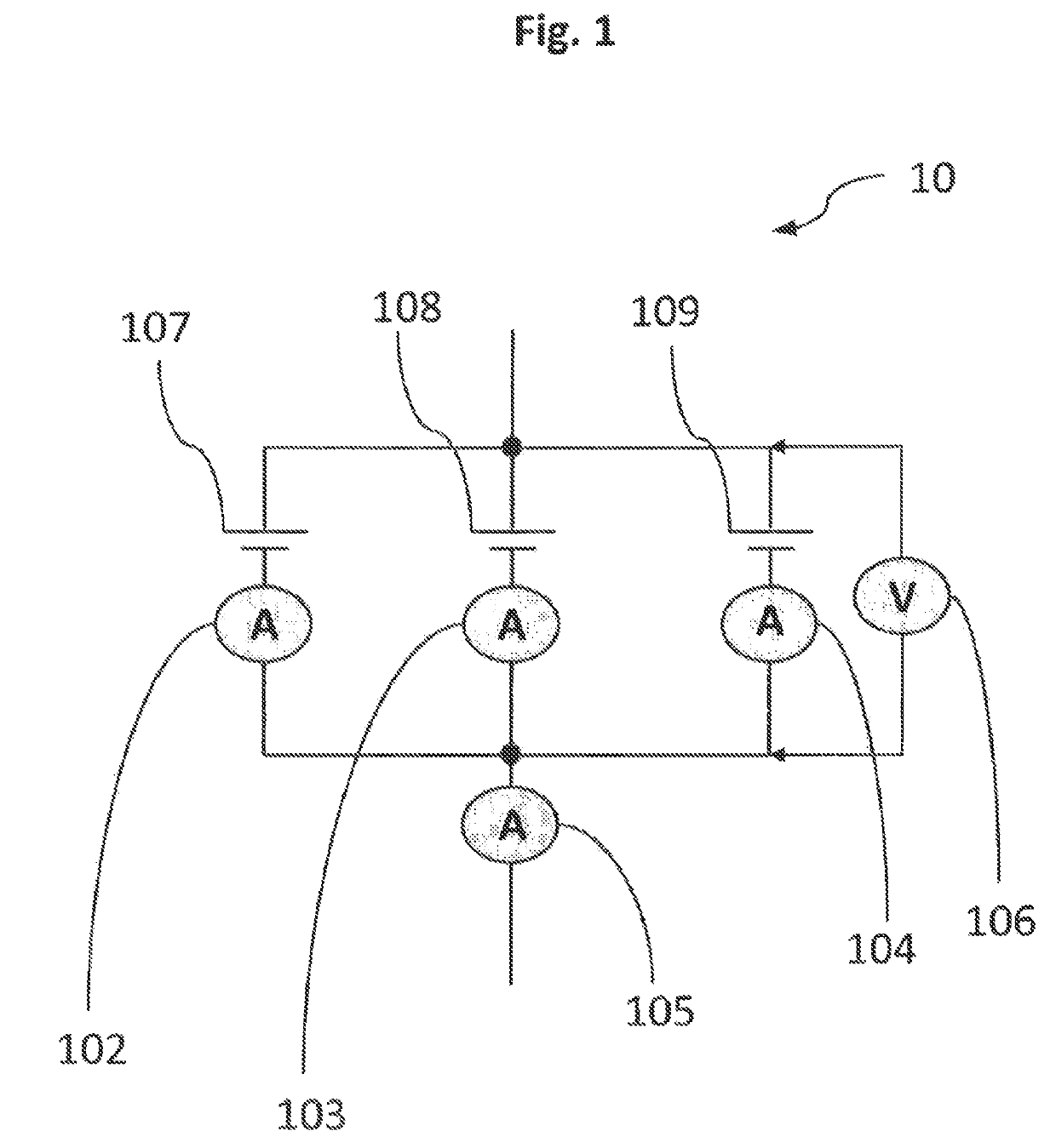
[0027]FIG. 1 shows a schematic representation of the disclosed electrical energy storage device 10 with three electrical energy storage units 107, 108, 109, which are electrically connected to each other in parallel. Using current sensors 102, 103, 104, a current flowing into each corresponding electrical energy storage unit is recorded. The recorded current amplitudes are then forwarded to a battery management controller, not shown here. Similarly, by means of a current sensor 105 the total current, which consists of the individual strands, is recorded. This recorded current amplitude is also forwarded to the battery management controller, not shown here. Using a voltage sensor 106, an electrical voltage of the parallel connected electrical energy storage units is recorded. Due to the parallel connection, the recorded voltage is essentially identical for all the electrical ...


PUM


Abstract

A method for detecting an internal short circuit in a first electrical energy storage unit of an electrical energy storage device is described, wherein the electrical energy storage device comprises at least two electrical energy storage units including a first electrical energy storage unit and a second electrical energy storage unit electrically connected in parallel in the electrical energy storage device, the method including recording an electric current flowing into or out of the first electrical energy storage unit, recording an electric current flowing into or out of the second electrical energy storage unit, determining a short-circuit current in the first electrical energy storage unit based on the at least two recorded electric currents, and detecting an internal short circuit when the magnitude of the short-circuit current exceeding a predefined short-circuit current threshold.

Description

BACKGROUND OF THE INVENTION[0001]The present invention is based on a method for detecting an internal short circuit in a first electrical energy storage unit of an electrical energy storage device, wherein the electrical energy storage device comprises at least two electrical energy storage units, a first electrical energy storage unit and a second electrical energy storage unit, which are electrically connected in parallel in the electrical energy storage device.[0002]In the course of the increasing electrification of vehicles, in particular motor vehicles, large electrical energy storage devices that consist of a plurality of smaller units are increasingly being used. These are usually in the form of battery packs, which are formed of a plurality of battery modules or battery cells. To ensure the safety of these energy storage devices, parameters such as an electric current and an electrical voltage of the electrical energy storage device or its smaller constituent units are usual...

Claims


Application Information

Patent Timeline
IPC IPC(8): H01M10/48G01R31/389H01M10/42G01R31/02G01R19/165
CPCH01M10/482G01R31/389H01M10/425G01R31/025G01R19/16542H01M2010/4271H01M2220/20G01R19/10G01R31/392G01R31/36G01R31/50H01M10/4207G01R31/52Y02E60/10
Inventor BERGMANN, SVENTZIVANOPOULOS, CHRYSANTHOSSWOBODA, JOHANNES
Owner ROBERT BOSCH GMBH
Learn More