
Battery and manufacturing method thereof

a technology of battery and manufacturing method, applied in the field of battery, can solve the problems of defective connection, damage unstable electrical connection between the electrode and the terminal, etc., and achieve the effect of preventing the damage to the electrode body, stably inserted, and effective reduction of the load applied to the electrode tab group

Pending Publication Date: 2022-05-05
PRIME PLANET ENERGY & SOLUTIONS INC
View PDF6 Cites 3 Cited by
  • Summary
  • Abstract
  • Description
  • Claims
  • Application Information

AI Technical Summary

Benefits of technology

The patent aims to improve the reliability of conduction in batteries by preventing damage to the electrode tab group. The invention involves providing an insulating member with protrusions that act as a spacer to reduce the load on the electrode lab group. This results in better performance and reliability of the battery.

Problems solved by technology

When a battery is used, vibration, an impact or the like may be applied to the battery from the outside.
For this reason, when an electrode body deviates from a predetermined arrangement position due to an external force and moves toward a sealing plate, an electrode tab group (a positive electrode tab group and / or a negative electrode tab group) may be damaged.
As a result, there is a concern that electrical connection between an electrode and a terminal may become unstable or defective connection may occur.

Method used


Image

  • Battery and manufacturing method thereof
  • Battery and manufacturing method thereof
  • Battery and manufacturing method thereof

Examples


second embodiment

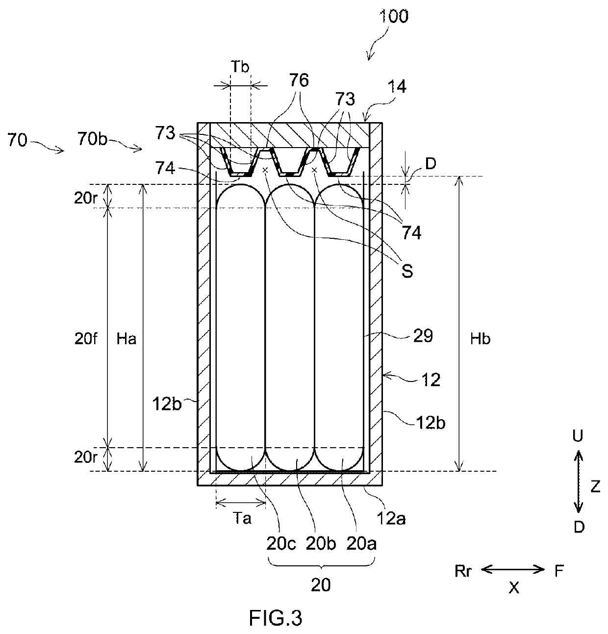
[0108]FIG. 13 is a diagram corresponding to FIG. 3 and shows a battery 200 according to a The battery 200 may be the same as the battery 100 except that a positive electrode insulating member 270 is included instead of the positive electrode insulating, member 70. The positive electrode insulating member 270 includes one protrusion portion 270b having a rectangular cross-section.

third embodiment

[0109]FIG. 14 is a diagram corresponding to FIG. 3 and shows a battery 300 according to a The battery 300 may be the same as the battery 100 except that a positive electrode insulating member 370 is included instead of the positive electrode insulating member 70. The positive electrode insulating member 370 includes a protrusion portion 370b having one rectangular portion 371 having a rectangular cross-section, and a plurality of protruding rib portions 372 protruding from the rectangular portion 371 to the electrode bodies 20a, 20b, and 20c sides.

fourth embodiment

[0110]FIG. 15 is a diagram corresponding to FIG. 3 and shows a battery 400 according to a The battery 400 may be the same as the battery 100 except that a positive electrode insulating member 470 is included instead of the positive electrode insulating member 70. The positive electrode insulating member 470 includes a protrusion portion 470b having a square-shaped cross-section. The protrusion portion 470b is hollow, and a gas flow path space 84 is secured therein.


PUM

PropertyMeasurementUnit
distanceaaaaaaaaaa
distanceaaaaaaaaaa
distanceaaaaaaaaaa

Abstract

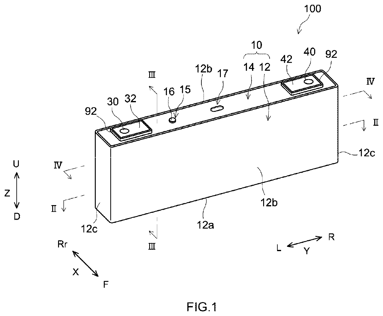
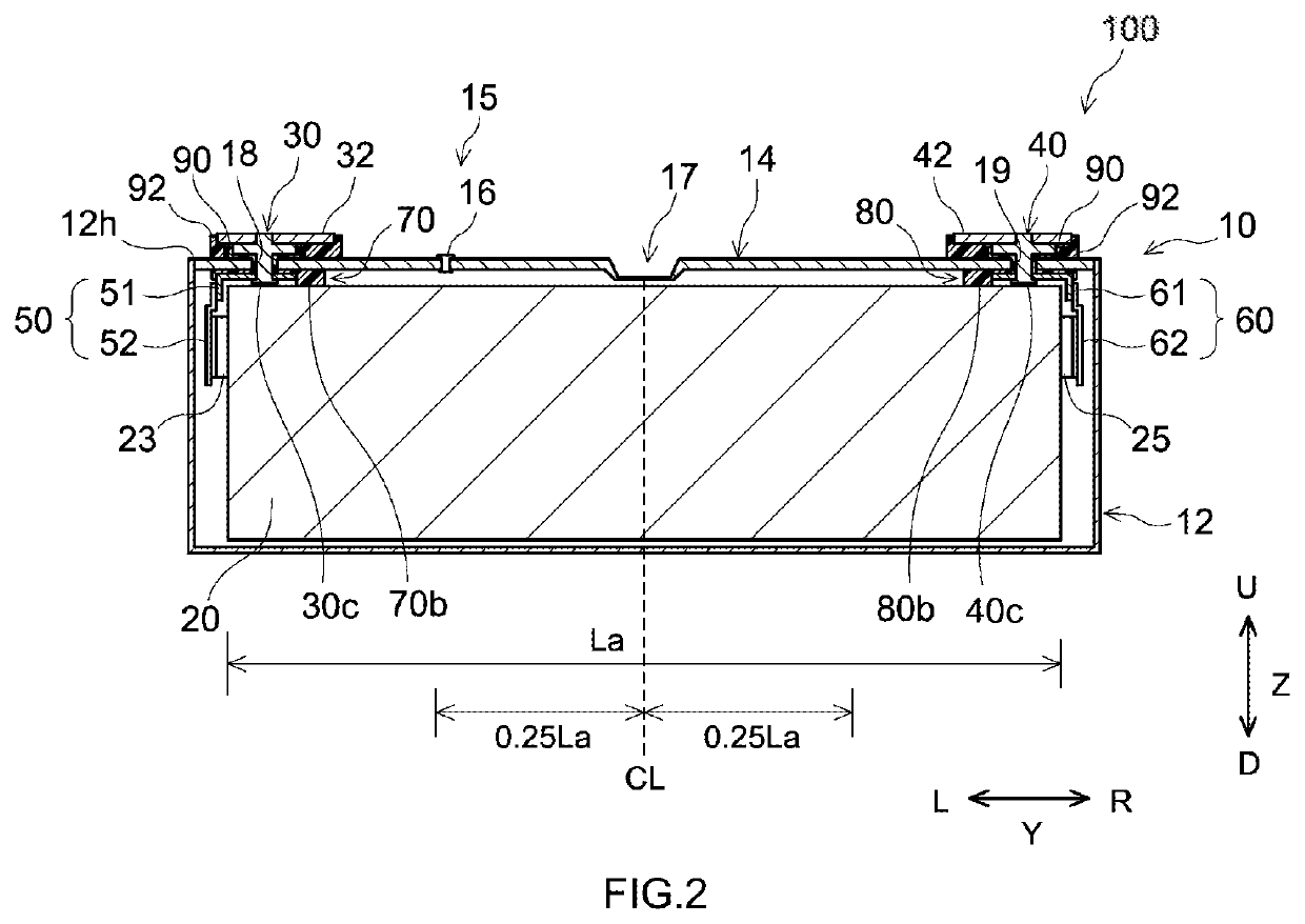
A battery disclosed herein includes an exterior body, a sealing plate sealing an opening of the exterior body, electrode bodies each including a first electrode, an electrode tab group electrically connected to the first electrodes, a terminal attached to the sealing plate and electrically connected to the electrode tab group, a collecting unit electrically connecting the electrode tab rid the terminal, and an insulating member insulating the sealing plate and the collecting unit from each other. The insulating member includes a base portion disposed between the sealing plate and the collecting unit, and protrusion portions protruding, from the sealing plate toward the sides of the electrode bodies.

Description

CROSS-REFERENCE TO RELATED APPLICATIONS[0001]The application is based on Japanese Patent Application No. 2020-185188 filed on Nov. 5, 2020, the content of which is incorporated herein by reference.BACKGROUND OF THE INVENTION1. Field of the Invention[0002]The present teaching relates to a battery and a manufacturing method thereof.2. Description of the Related Art[0003]A battery such as a lithium ion secondary battery generally includes an electrode body including an electrode, an exterior body including an opening and accommodating the electrode body, a sealing plate sealing the opening of the exterior body, and a terminal electrically connected to the electrode inside the exterior body and extending from the sealing plate to the outside of the exterior body. In such a type of battery, a configuration, in which an electrode tab group including a plurality of tabs for current collecting is provided in the electrode and the electrode is connected to a terminal through the electrode ta...

Claims


Application Information

Patent Timeline
Patent Type & Authority Applications(United States)
IPC IPC(8): H01M50/538H01M50/593H01M50/186H01M50/35H01M10/04
CPCH01M50/538H01M50/593H01M10/0431H01M50/35H01M50/186H01M50/59H01M50/586H01M50/536H01M10/0587H01M10/0525H01M50/176H01M50/183H01M50/30H01M50/474H01M50/477H01M50/543Y02E60/10Y02P70/50H01M50/209H01M50/531
Inventor WAKIMOTO, RYOICHI
Owner PRIME PLANET ENERGY & SOLUTIONS INC
Learn More