Illuminated door handle

a technology of door handles and light bulbs, applied in the field of door handles, can solve the problems of increasing the number of members, the connection state between the connection code and the circuit board may become unstable, and the circuit board may deform, so as to avoid an increase in the manufacturing cost and reduce the load applied to the circuit board

Active Publication Date: 2016-10-13
KOITO MFG CO LTD +1
View PDF4 Cites 6 Cited by
  • Summary
  • Abstract
  • Description
  • Claims
  • Application Information

AI Technical Summary

Benefits of technology

[0009]The invention provides a door handle that makes it possible to reduce the load applied to the circuit board while avoiding an increase in the manufacturing cost.

Problems solved by technology

As a result, the circuit board may deform or the connection state between the connection code and the circuit board may become unstable.
On the other hand, in a case where a dedicated support member for supporting the connection code is used in order to prevent the load from applying to the circuit board, the number of the members increases, which leads to the high manufacturing cost.

Method used


Image

  • Illuminated door handle
  • Illuminated door handle
  • Illuminated door handle

Examples


Embodiment Construction

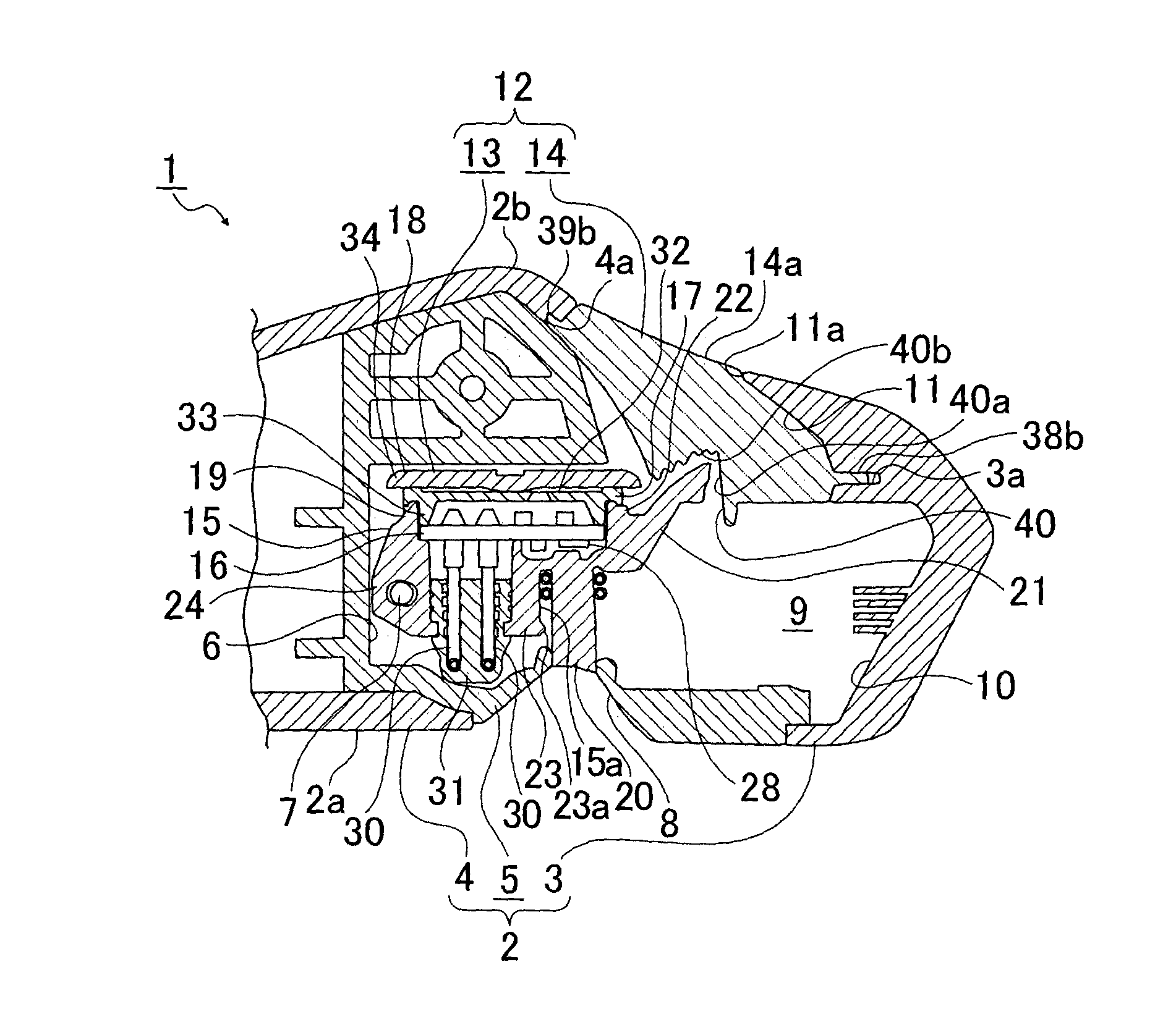
[0029]Hereinafter, an embodiment of a door handle according to the invention is explained with reference to the drawings.

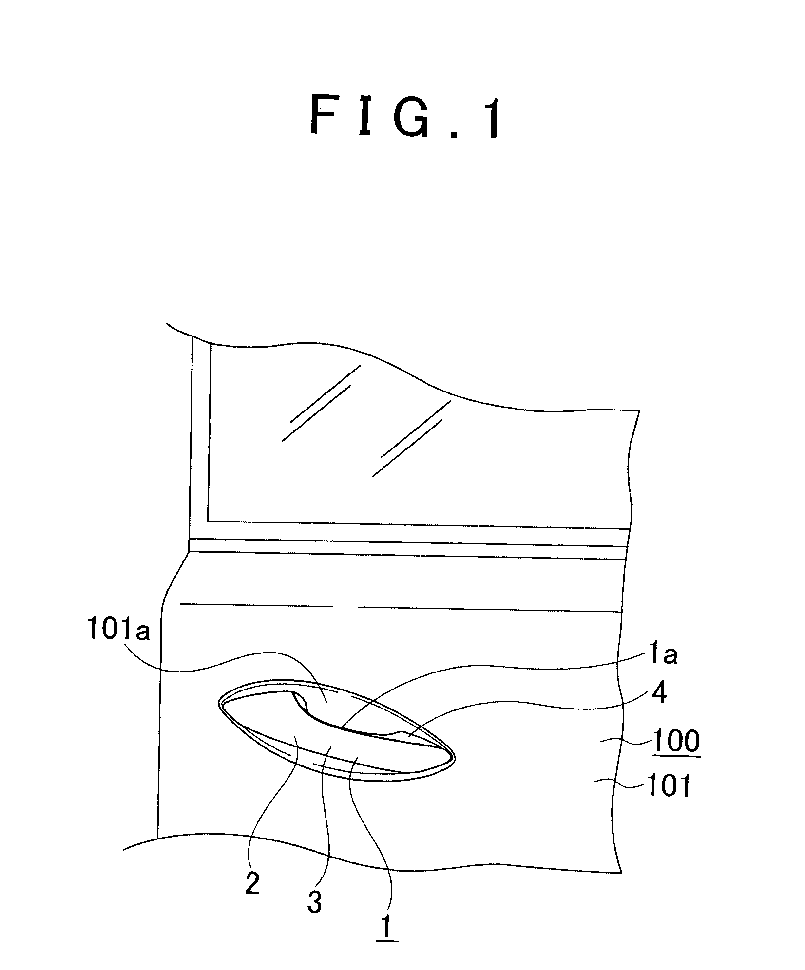
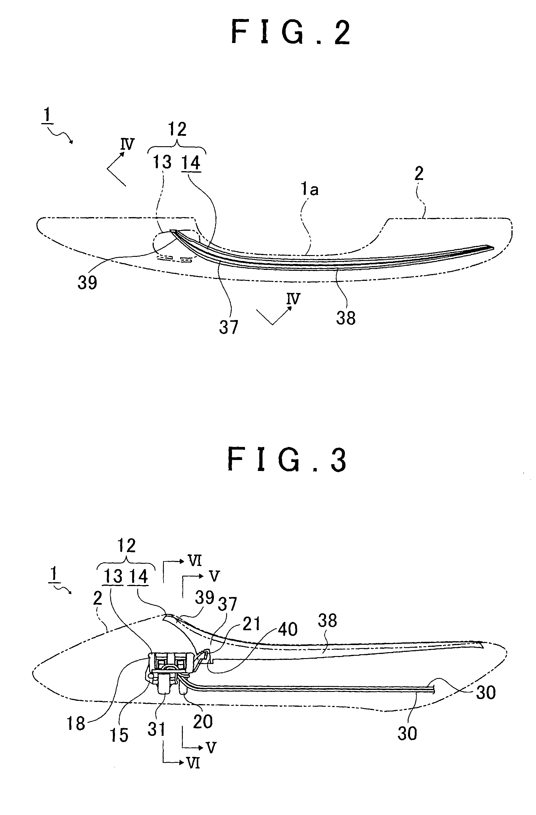
[0030]A door handle 1 is used as a handle provided for a door 100 of a vehicle. The door handle 1 has a shape extending in a front-rear direction of the vehicle, for example, and includes a casing 2 and a lamp unit 12 disposed inside the casing 2, which will be described later (FIGS. 1 to 3). A joint portion of the door handle 1, which is provided at a front end portion thereof and not shown in the drawings, is joined to a door panel 101 (FIG. 1). A panel concavity 101a is formed in an outer surface of the door panel 101. The panel concavity 101a accommodates user's (occupant's) fingers put in an inner side of the door handle 1.

[0031]The door handle 1 pivots about the front end portion such that a rear end portion thereof moves in a right-left direction of the vehicle. When the door 100 is opened, the door handle 1 is caused to pivot by the user's operation in a d...


PUM


Abstract

A door handle includes a casing inside which an accommodation space is provided, and a lamp unit disposed in the accommodation space. The lamp unit includes a light emission element, a circuit board on which the light emission element is mounted, and a combination member including a housing and a light guiding lens. The housing supports the circuit board, and the light guiding lens guides light emitted from the light emission element in a predetermined direction. In the door handle, a connection wire that supplies driving current to at least the light emission element is connected to the circuit board, and a portion of the connection wire is wound around a portion of the combination member.

Description

BACKGROUND OF THE INVENTION[0001]1. Field of the Invention[0002]The invention relates to a door handle provided with a lamp unit including a circuit board on which a light emission element is mounted.[0003]2. Description of Related Art[0004]In some door handles, a circuit board is supported by a housing, a light emission element that functions as a light source is mounted on the circuit board, and light emitted from the light emission element is radiated in a predetermined direction (for example, see Japanese Patent Application Publication 2010-229797 (JP-A-2010-229797), Japanese Patent Application Publication 2009-133133 (JP-A-2009-133133), and Japanese Patent Application Publication 2006-9279 (JP-A-2006-9279)).[0005]JP-A-2010-229797 and JP-A-2009-133133 describe a light unit provided in a door handle that illuminates an area around the user's feet when a door is opened or closed. By illuminating the area around the user's feet, the user can see whether there is a puddle or the lik...

Claims


Application Information

Patent Timeline
Patent Type & Authority Applications(United States)
IPC IPC(8): B60Q1/26E05B85/16
CPCB60Q1/2669E05B17/10B60Q2400/40E05B85/16E05B79/06E05B85/10F21S43/14F21S43/195F21S43/241F21S43/251
Inventor TAKAHASHI, HARUHITOKAZAOKA, SHIGEHIKOTATEISHI, MASASHIYOSHINO, MASAKIISHIKAWA, YOSHIKI
Owner KOITO MFG CO LTD
Why Eureka
Try Eureka