
Ablating material for an object in a particle beam device

Pending Publication Date: 2022-04-28
CARL ZEISS MICROSCOPY GMBH
View PDF7 Cites 1 Cited by
  • Summary
  • Abstract
  • Description
  • Claims
  • Application Information

AI Technical Summary

Benefits of technology

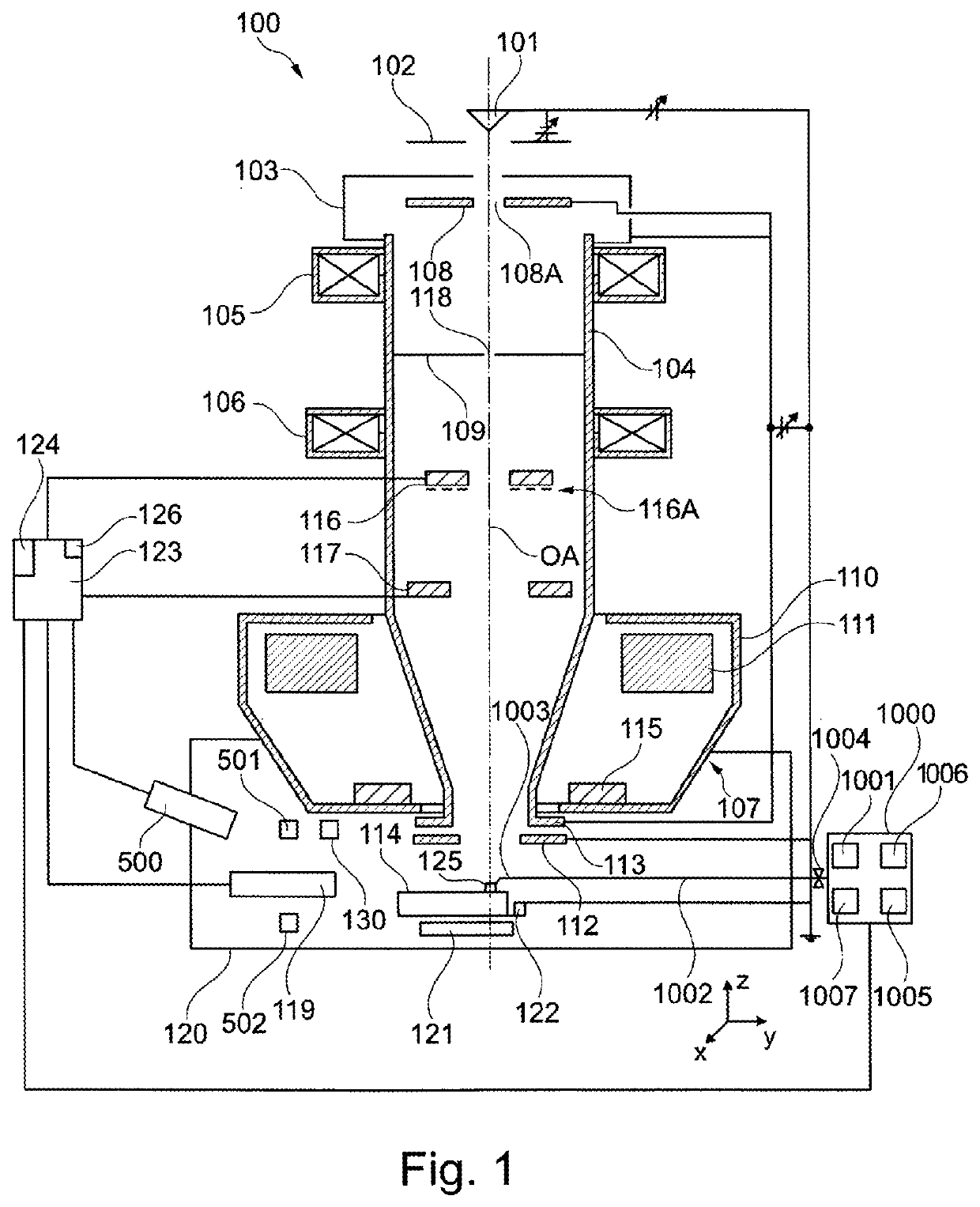
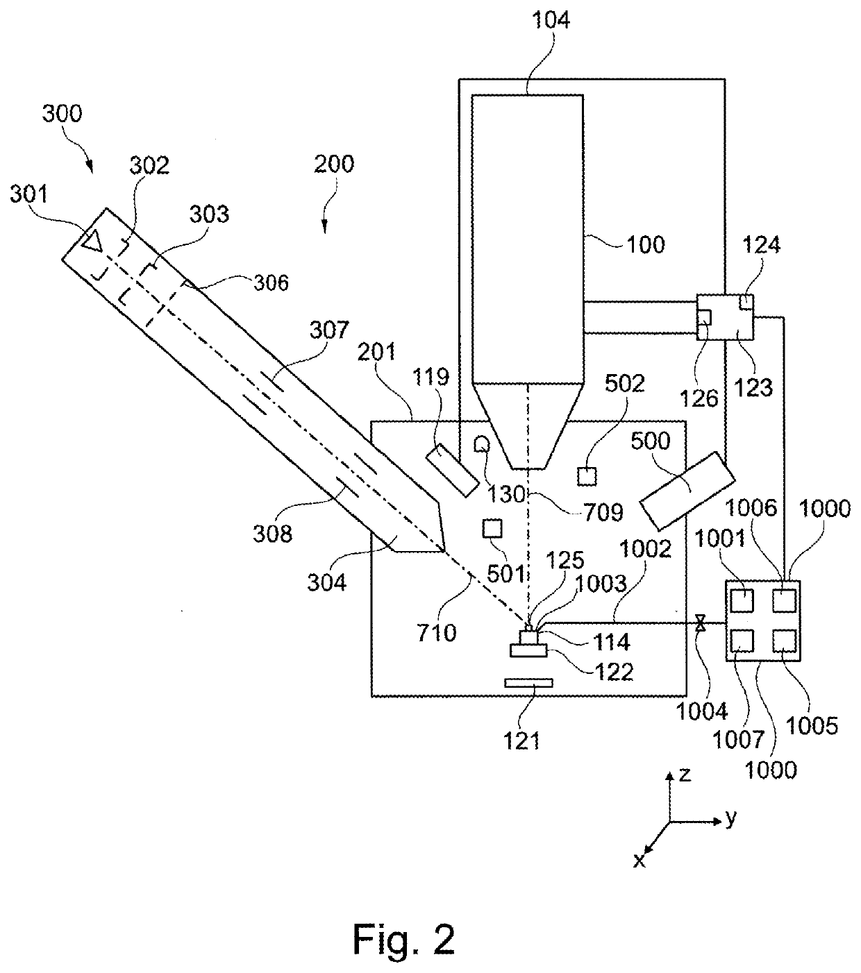
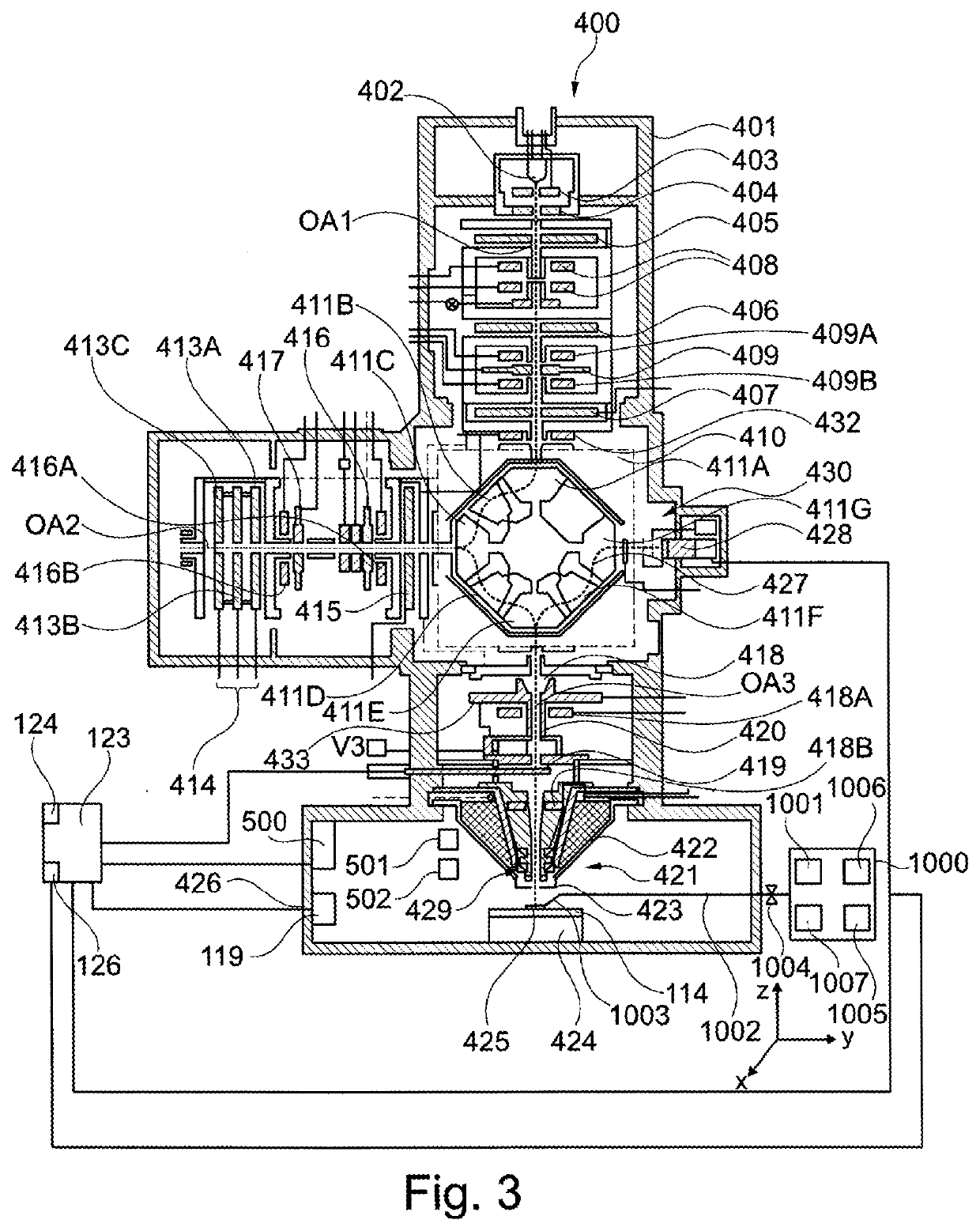
The system described in this patent allows for the arrangement of different materials on an object using a particle beam. It can also define the location on the surface of the object where the material is being arranged. The system uses a mask or an aperture to define the location. The method involves applying a first voltage between the material and the object to guide the ablated material from the material unit to the object. A gas, like water vapor, can also be used to increase the ionization of the ablated material. The structural unit, like a manipulator or a sample carrier, can also have the ablatable material applied to it using the particle beam and a second gas feed device. This allows for precise placement of the material and increased flow of the ionized material to the surface of the object.

Problems solved by technology

However, the force exerted on the part of the object can affect the part of the object undesirably, up to the destruction of the part of the object.
However, on account of residual gases present in the sample chamber there is contamination of the coating when such a coating is generated by the interaction of the ion beam with a precursor.
Moreover, the number of currently available precursors is limited, and so it is not possible to arbitrarily choose the material to be deposited.

Method used


Image

  • Ablating material for an object in a particle beam device
  • Ablating material for an object in a particle beam device
  • Ablating material for an object in a particle beam device

Examples


first embodiment

[0158]FIG. 6 shows the material unit 502. The material unit 502 comprises a main body 505 and an end 506 adjoining the main body 505. The end 506 is embodied with a point in this embodiment.

second embodiment

[0159]FIG. 7 shows the material unit 502. The material unit 502 comprises a main body 505 and an end 506 adjoining the main body 505. The end 506 is embodied to be convex in this embodiment.

third embodiment

[0160]FIG. 8 shows the material unit 502. The material unit 502 comprises a main body 505 and an end 506 adjoining the main body 505. The end 506 is embodied to be flat in this embodiment. A first side in the form of a longitudinal side 507 of the material unit 502 is larger by a factor of ten, fifteen or twenty than a second side in the form of a transverse side 508 of the material unit 502.


PUM

PropertyMeasurementUnit
Timeaaaaaaaaaa
Electric potential / voltageaaaaaaaaaa
Distanceaaaaaaaaaa

Abstract

The invention relates to a method for ablating a material (1) from a material unit (502) and for arranging the material (1) on an object (125), the object (125) being arranged in a particle beam apparatus. Further, the invention relates to a computer program product, and to a particle beam apparatus for carrying out the method. The method comprises feeding a particle beam with charged particles onto the material (1), wherein the material (1) is arranged on the material unit (502) and / or wherein the material unit (502) is formed from the material (1), wherein the material (1) is ablatable from the material unit (502) and wherein the material (1) is arranged on the material unit (502) at a distance from the object (125).Further, the method comprises ablating the ablatable material (1) arranged on the material unit (502) from the material unit (502) using the particle beam, and arranging the ablated material (514) on the object (125).

Description

CROSS-REFERENCE TO RELATED APPLICATIONS[0001]This application claims the priority of the German patent application No. 10 2020 112 220.9, filed on May 6, 2020, which is incorporated herein by reference.TECHNICAL FIELD[0002]The system described herein relates to ablating at least one material from a material unit and for arranging the material on an object, the object being arranged in a particle beam apparatus. Further, the system described herein relates to a computer program product, and to a particle beam apparatus for ablating at least one material from a material unit and for arranging the material on an object. The particle beam apparatus is embodied as an electron beam apparatus and / or as an ion beam apparatus, for example.BACKGROUND[0003]Electron beam apparatuses, in particular a scanning electron microscope (also referred to as SEM) and / or a transmission electron microscope (also referred to as TEM), are used to examine objects (samples) in order to obtain knowledge with re...

Claims


Application Information

Patent Timeline
IPC IPC(8): H01J37/305H01J37/20
CPCH01J37/3053H01J37/10H01J2237/202H01J37/20G01N23/2258G01N23/2251G01N23/2206G01N2223/072H01J2237/208H01J37/3056H01J2237/31745H01J2237/31749H01J2237/006C23C14/221C23C14/46C23C14/345C23C14/505C23C14/28C23C14/30
Inventor DOEMER, HOLGERNICOLETTI, MICHELESCHMAUNZ, ANDREAS
Owner CARL ZEISS MICROSCOPY GMBH
Learn More