
Vehicle braking control device

Active Publication Date: 2022-04-21
ADVICS CO LTD
View PDF0 Cites 0 Cited by
  • Summary
  • Abstract
  • Description
  • Claims
  • Application Information

AI Technical Summary

Benefits of technology

The present disclosure provides a vehicle braking control device that can achieve both directional stability and deceleration performance of a vehicle during an anti-skid control when the vehicle is turning or on a split coefficient of friction surface. The device uses the yaw rate to determine the outside and inside of a turn and calculates a deflection index based on the steering angle and actual turning amount to reduce the braking torque of the rear wheel on the outside of the turn when excessive deceleration slip is inhibited. This allows for sufficient deceleration and shorter braking distance. Additionally, the device can determine which rear wheel is on a higher or lower coefficient of friction road surface and adjust the brake torque accordingly to maintain directional stability and deceleration performance on the split coefficient of friction road surface.

Problems solved by technology

Directional stability and deceleration performance of the vehicle may unfavorably interfere with each other during the execution of the anti-skid (or anti-lock brake or ABS) control.

Method used


Image

  • Vehicle braking control device
  • Vehicle braking control device
  • Vehicle braking control device

Examples


Embodiment Construction

{Reference Letters and Numerals of Configuring Members, etc., Letters at the End of the Reference Letters and Numerals, and Notion / Moving Direction}

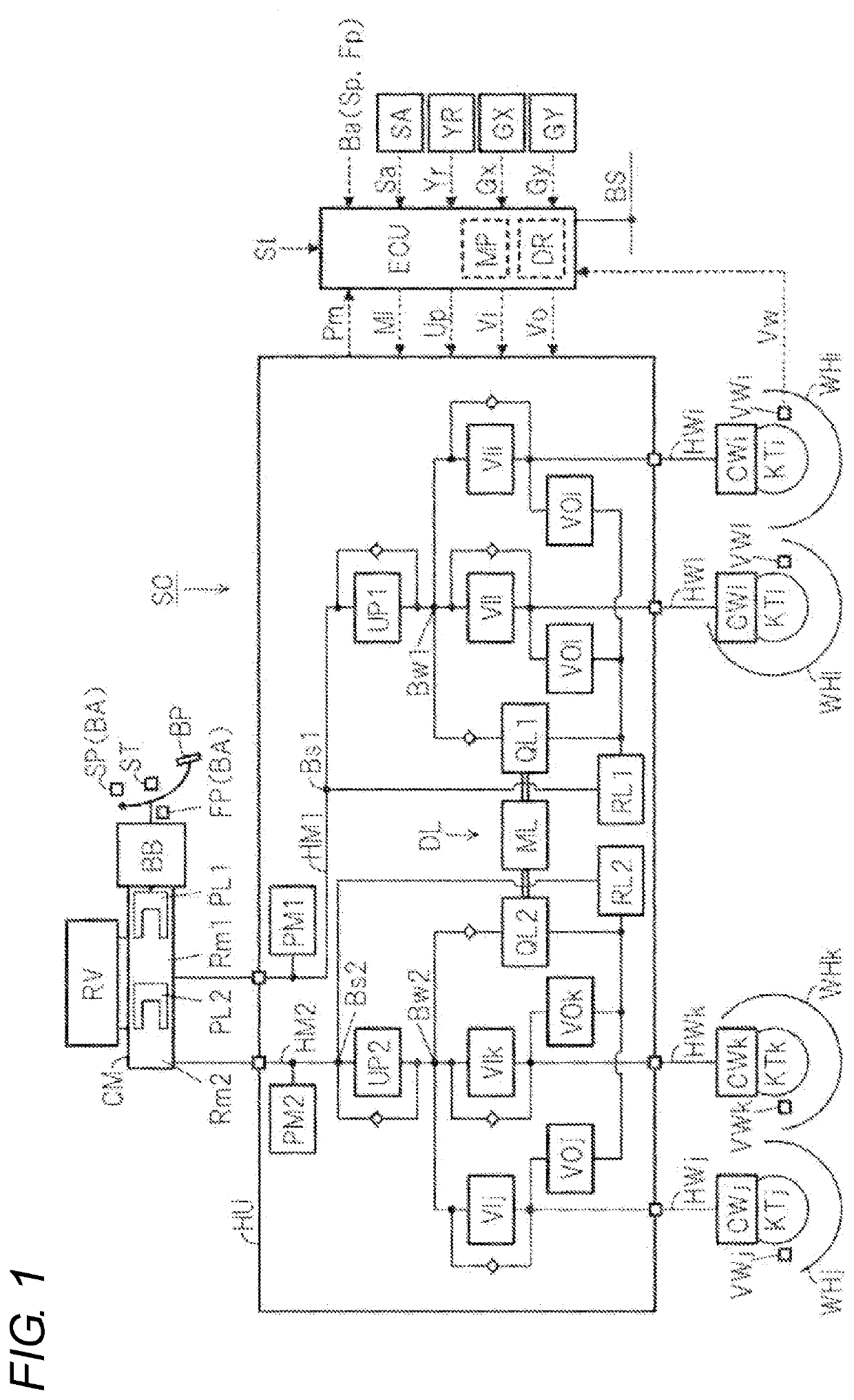
[0018]In the following description, configuring members, calculation processes, signals, characteristics, and values having the same reference letters such as “ECU” have the same functions. The letters at the end of reference letters and numerals, such as “i” to “l”, are comprehensive letters indicating which wheel they relate to. Specifically, “i” indicates a right front wheel, “j” indicates a left front wheel, “k” indicates a right rear wheel, and “l” indicates a left rear wheel. For example, each of the four wheel cylinders is described as wheel cylinder CWi of the right front wheel, wheel cylinder CWj of the left front wheel, wheel cylinder CWk of the right rear wheel, and wheel cylinder CW1 of the left rear wheel. Furthermore, the letters “i” to “l” at the end of the reference letters and numerals can be omitted. When the letters “i...


PUM


Abstract

In a braking control device, a controller is configured to determine an inside and an outside of a turn by using the yaw rate, to calculate a deflection index based on a standard turning amount corresponding to a steering angle and an actual turning amount corresponding to a yaw rate, to reduce the braking torque of the rear wheel on the outside of the vehicle turn based on the deflection index when an excessive deceleration slip of the rear wheel on the inside of the vehicle turn is inhibited during an execution of anti-skid control.

Description

TECHNICAL FIELD[0001]The present disclosure relates to a vehicle braking control device.BACKGROUND ART[0002]Patent Literature 1 describes, for the purpose of improving the control quality of a brake control device that performs the ABS control, providing on a control unit k that includes a control amount determination unit kl for determining a control amount of an ABS unit e based on an input from a vehicle behavior detection means g and executes the ABS control for preventing the wheels from being locked at the time of braking, a control wheel speed calculation unit k2 that obtains each wheel speed from a detected value of a wheel speed sensor f, a turning determination unit k4 that determines a turning state based on a vehicle body left side speed and a vehicle body right side speed obtained from a vehicle body left and right side speed calculation unit k3, and rear wheel speed determination unit k5 that determines the way of obtaining the wheel speed for control of the rear wheel...

Claims


Application Information

Patent Timeline
IPC IPC(8): B60T8/1755B60T8/1764
CPCB60T8/1755B60T8/1764B60T2250/03B60T2250/04B60T2260/024B60T2201/16B60T2210/124
Inventor TERASAKA, MASATOKITAHARA, CHISA
Owner ADVICS CO LTD
Learn More