Prepreg manufacturing method and manufacturing apparatus
- Summary
- Abstract
- Description
- Claims
- Application Information
AI Technical Summary
Benefits of technology
Problems solved by technology
Method used
Image
Examples
example 1
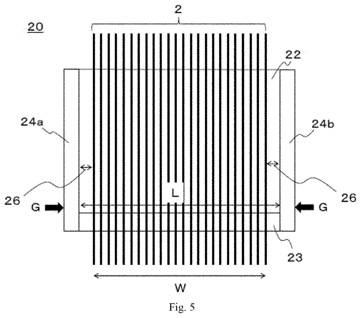
[0181]In the present Example, a prepreg was produced using the external force application mechanisms 50a to 50f totaling six units, three each in the width direction on the wall constituent members 21e and 21f, as shown FIG. 18. Out of these, the external force application mechanisms 50c and 50d were disposed so as to match the center of the wall constituent members 21e and 21f respectively in the width direction and the center of the narrowed section in the width direction, and the spacing (La) between adjacent external force application mechanisms was 100 mm. In addition, external force application mechanisms 50 of an adjusting bolt type shown in FIG. 19 were used as the external force application mechanisms 50a to 50f in the present Example. Furthermore, in the vicinity of the external force application mechanisms 50a to 50f, contact displacement gauges (dial gauges manufactured by Mitutoyo Corporation) were mounted as measurement devices 52a to 52f respectively for measuring the...
example 2
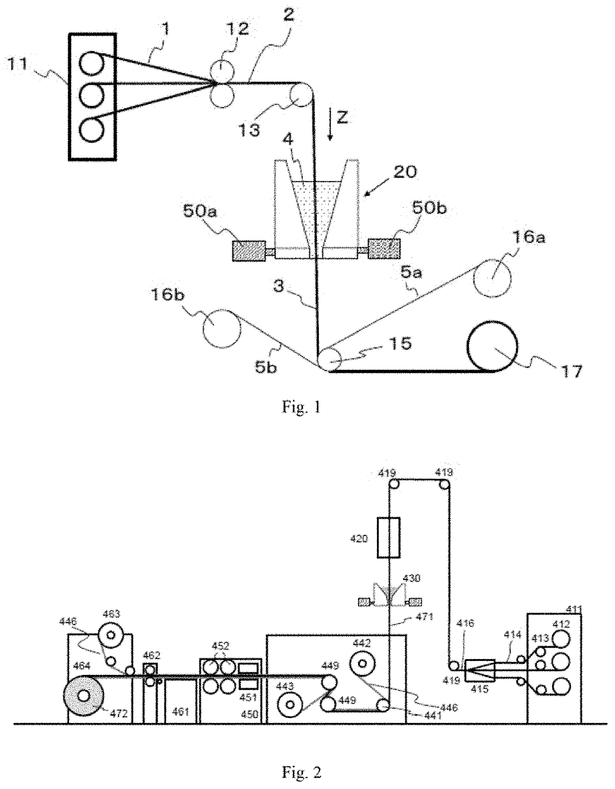
[0185]The coating section 20c of the type depicted in FIG. 9 was used as a coating section, and an apparatus configured as depicted in FIG. 2 and further including a thickness gauge (see FIG. 21; the same in Examples 3 to 13 and Comparative Examples 2 and 3) was used as an apparatus for producing a prepreg. The liquid pool 22 was tapered (the opening angle of the upper taper was 17°, and the opening angle of the lower taper was) 7°. However, the width of the outlet of the narrowed section was 306 mm. In this regard, the gap D in the narrowed section 23 was 0.2 mm, and thus, the aspect ratio of the outlet slit was 1530. In addition, 15 external force application mechanisms of a heat bolt type having a structure depicted in FIG. 20 were mounted at 20 mm intervals on each side of the narrowed section, which was thus sandwiched by the mechanisms (see FIG. 18). A column having a diameter of 10 mm and made of SUS430 (having a thermal conductivity of 15W / m·° C.) was used as a rod 55 of the...
examples 3 to 9
[0188]A prepreg was produced and evaluated in the same manner as in Example 2 except that the number of external force application mechanisms and the spacing therebetween were changed as in Table 2. At any level, it was possible to take a sample which was rated as usable or better. The results are shown in Table 2.
PUM
| Property | Measurement | Unit |
|---|---|---|
| Temperature | aaaaa | aaaaa |
| Length | aaaaa | aaaaa |
| Thickness | aaaaa | aaaaa |
Abstract
Description
Claims
Application Information
 - R&D
- Intellectual Property
- Life Sciences
- Materials
- Tech Scout
- Unparalleled Data Quality
- Higher Quality Content
- 60% Fewer Hallucinations
Browse by: Latest US Patents, China's latest patents, Technical Efficacy Thesaurus, Application Domain, Technology Topic, Popular Technical Reports.
© 2025 PatSnap. All rights reserved.Legal|Privacy policy|Modern Slavery Act Transparency Statement|Sitemap|About US| Contact US: help@patsnap.com


