
Non-invasively adjustable spinal stabilization device

Pending Publication Date: 2022-04-14
PEYMAN NAZMI +1
View PDF15 Cites 0 Cited by
  • Summary
  • Abstract
  • Description
  • Claims
  • Application Information

AI Technical Summary

Benefits of technology

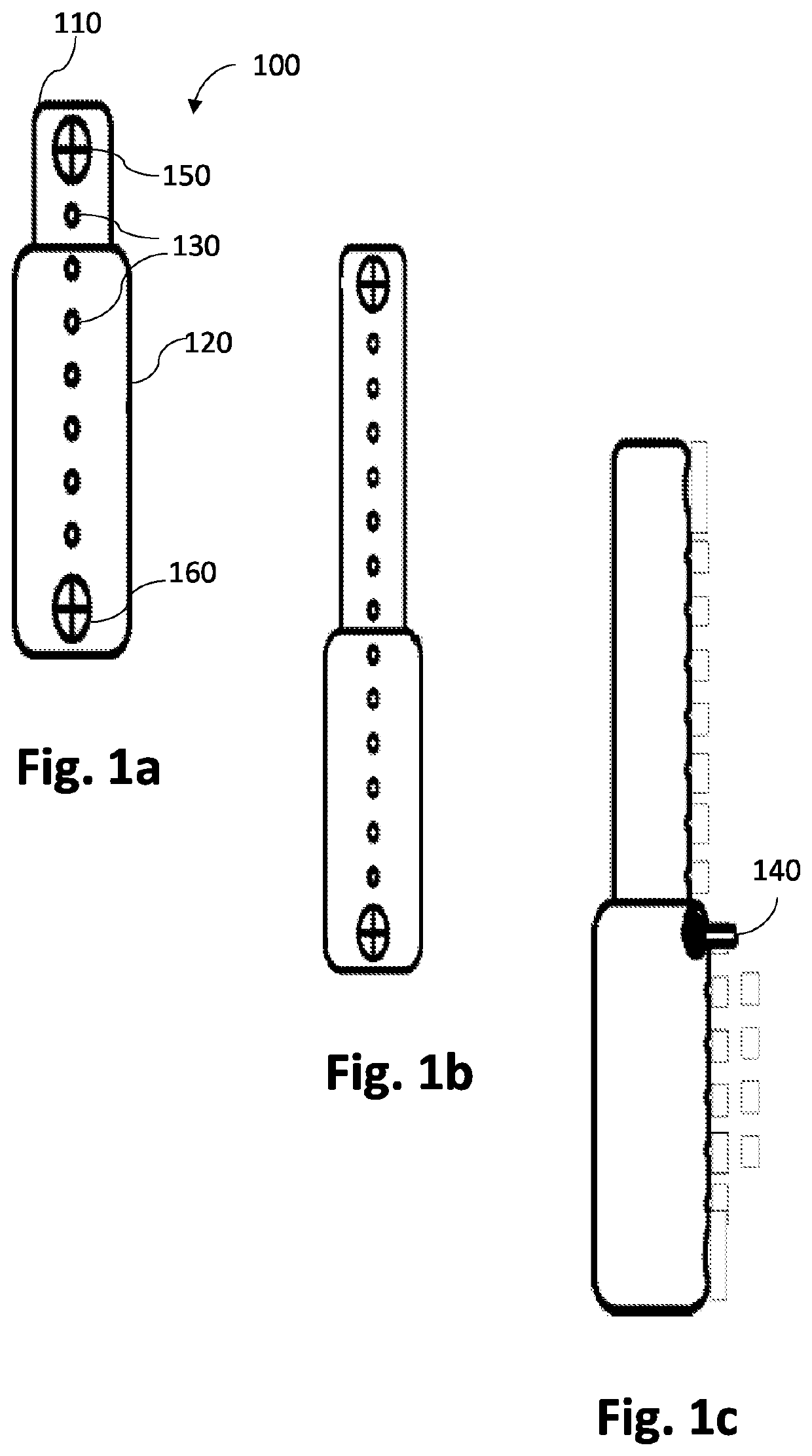
The present invention is a spinal stabilization device that has the technical effects of preventing the need for a subsequent invasive surgery to reconfigure the spinal implementation, reducing the duration of treatment, and reducing the overall cost of treatment. The device includes inner and outer tubes with multiple corresponding holes, and a fastener that can be inserted through a hole in the outer tubes into a hole in the inner tubes to restrict the movement of the inner tube. Optionally more than one pin can be provided that can be inserted in more than one hole simultaneously for additional strength.

Problems solved by technology

Degenerative changes of the spinal structures, such as intervertebral discs and facet joints can cause significant degrees of bodily pains, in particular, pain in the spine, legs, and arms.
Spinal stenosis is a common problem caused by narrowing of the spaces within the spinal canal, putting extra pressure on the spinal cord and spinal nerves.
Spinal stenosis is a leading cause of lower back pains.
However, spinal surgery is not always successful and often patients report a significant degree of pain after the surgery.
Upon the resulting activity after surgery, if the curvatures of the spine are not natural, it may potentially cause additional pain and discomfort.
Furthermore, even when the spine is fused in an optimum shape, curvature, and position during the surgery, over the long run, there may be more wear and tear and / or degeneration of tissues and spine, leading to pain and other medical conditions.
With the present technology, once the instrumentation is in place, it is not possible to modify its configuration without surgery.
Hence another and more complicated surgery is required.

Method used


Image

  • Non-invasively adjustable spinal stabilization device
  • Non-invasively adjustable spinal stabilization device
  • Non-invasively adjustable spinal stabilization device

Examples


Embodiment Construction

[0031]Subject matter will now be described more fully hereinafter with reference to the accompanying drawings, which form a part hereof, and which show, by way of illustration, specific exemplary embodiments. Subject matter may, however, be embodied in a variety of different forms and, therefore, covered or claimed subject matter is intended to be construed as not being limited to any exemplary embodiments set forth herein; exemplary embodiments are provided merely to be illustrative. Likewise, a reasonably broad scope for claimed or covered subject matter is intended. Among other things, for example, the subject matter may be embodied as methods, devices, components, or systems. The following detailed description is, therefore, not intended to be taken in a limiting sense.

[0032]The word “exemplary” is used herein to mean “serving as an example, instance, or illustration.” Any embodiment described herein as “exemplary” is not necessarily to be construed as preferred or advantageous ...


PUM


Abstract

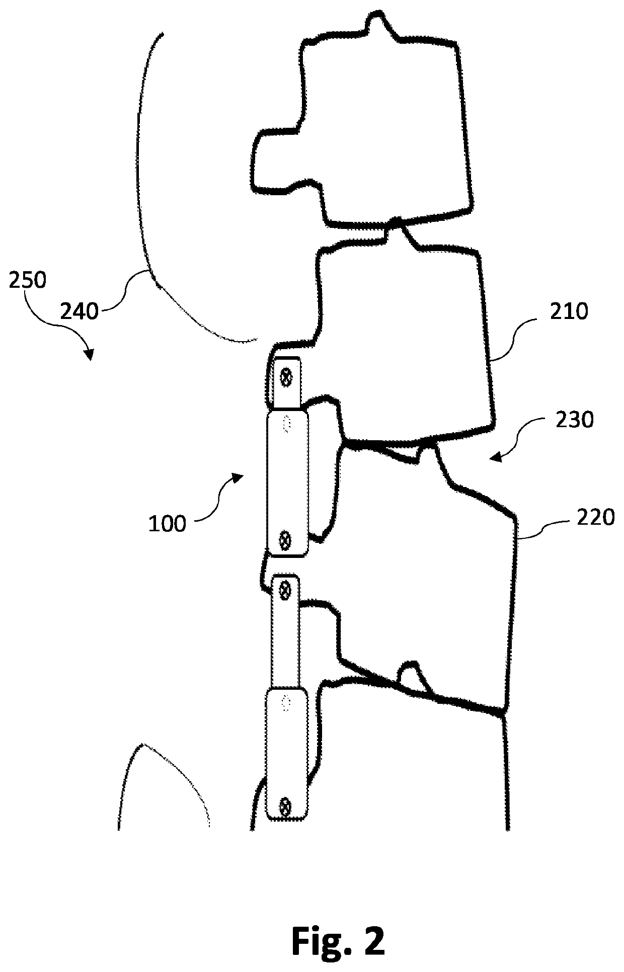
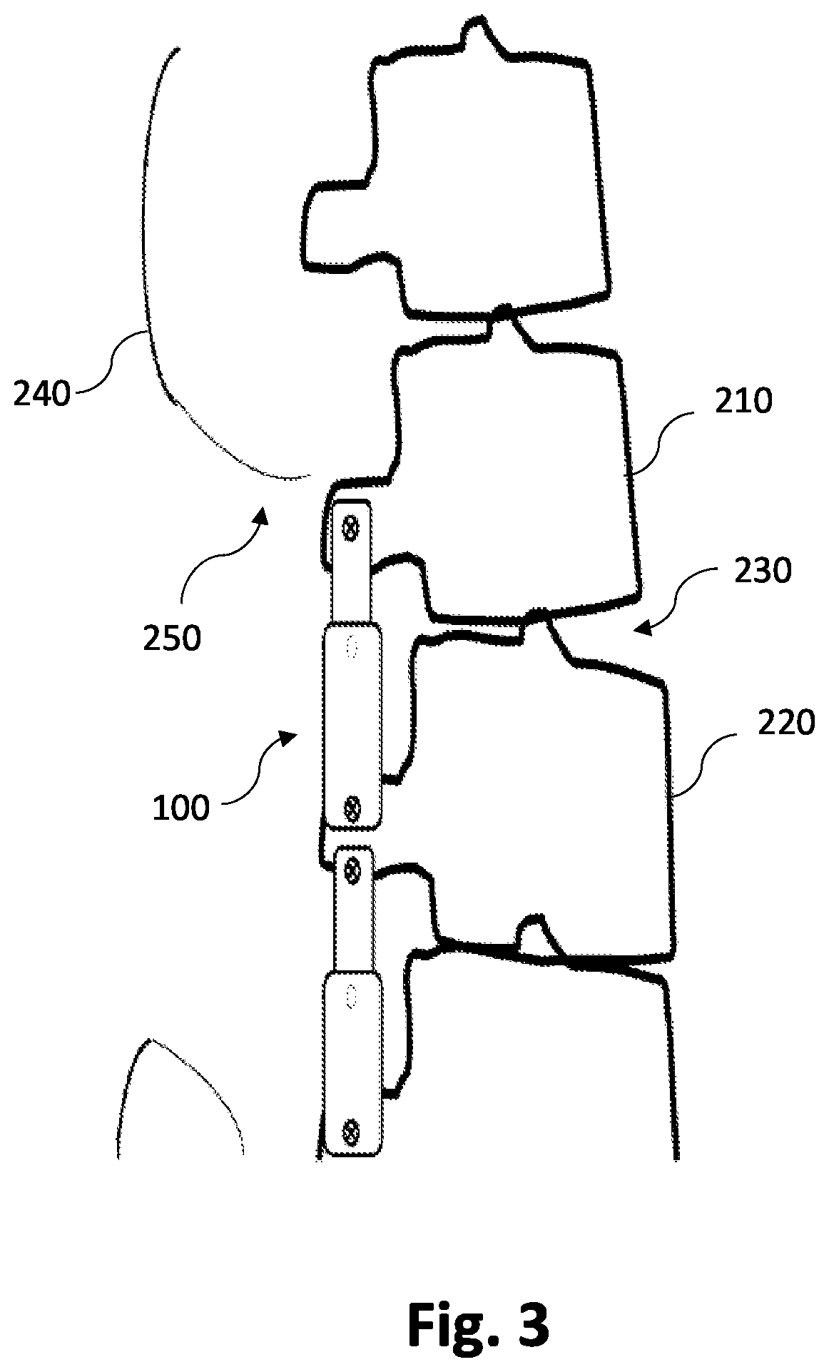
A spinal stabilization device that can be used to non-invasively correct spacing and curvature between at least two vertebral structures. The spinal stabilization device includes two telescoping tubes wherein ends of the two tubes can have pedicle screws that can be fastened to two or more vertebral bones. The overall length of the spinal stabilization device can be adjusted by moving the inner tube within the outer tube. Both the outer tube and the inner tube have multiple holes for receiving fasteners, wherein a fastener can be inserted through a hole in the outer tube into a hole in the inner tube for interlocking the inner tube and outer tube. The extension of the fastener into the holes and retraction from the holes can be controlled non-invasively from an external source. When the fastener is disengaged, the inner tube and the outer tube can freely move relative to each other, and the positions of the two or more vertebral bones can be non-invasively adjusted by subjecting a person to predefined movements and body posture. Upon achieving the desired positions, the fastener can be engaged to interlock the inner tube and the outer tube.

Description

CROSS-REFERENCE TO RELATED APPLICATIONS[0001]This application claims priority from the U.S. provisional patent application Ser. No. 63 / 090,959, filed on Oct. 13, 2020, which is incorporated herein by reference in its entirety.FIELD OF INVENTION[0002]The present invention relates to a spinal stabilization device, and more particularly, the present invention relates to a telescoping device that can be anchored to two or more vertebral structures.BACKGROUND[0003]Degenerative changes of the spinal structures, such as intervertebral discs and facet joints can cause significant degrees of bodily pains, in particular, pain in the spine, legs, and arms. Spinal stenosis is a common problem caused by narrowing of the spaces within the spinal canal, putting extra pressure on the spinal cord and spinal nerves. Spinal stenosis is a leading cause of lower back pains. Various factors, in particular increased age, sedentary lifestyle, or trauma are responsible for various degrees of spinal degenera...

Claims


Application Information

Patent Timeline
IPC IPC(8): A61B17/70
CPCA61B17/7016A61B2017/00221A61B2017/00991A61B2017/00411A61B2090/064A61B17/7014A61B17/7025A61B17/7011A61B2017/00477A61B2017/00876
Inventor PEYMAN, NAZMIZAHEDI, EDMOND
Owner PEYMAN NAZMI
Learn More