
Array substrate and display device thereof

a technology of array substrate and display device, applied in the field of array substrate, can solve the problems of low hole mobility, difficult control general adoption of horizontal channel length, etc., and achieve the effect of improving the yield of array substra

Inactive Publication Date: 2022-04-07
SHENZHEN CHINA STAR OPTOELECTRONICS SEMICON DISPLAY TECH CO LTD
View PDF0 Cites 0 Cited by
  • Summary
  • Abstract
  • Description
  • Claims
  • Application Information

AI Technical Summary

Benefits of technology

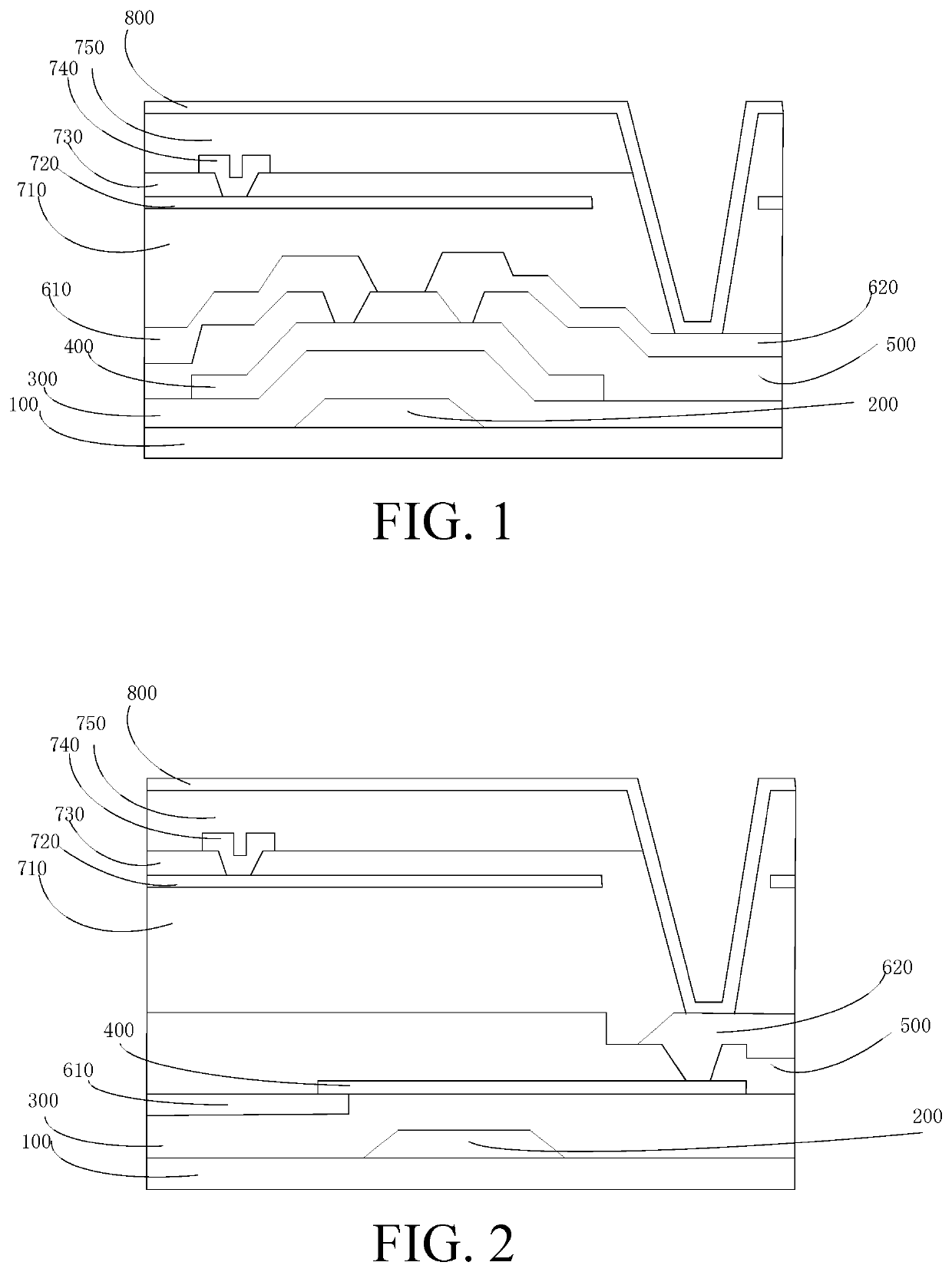
The present patent provides an array substrate and display device with improved yield. The substrate has a first signal electrode layer patterned to form a first signal electrode and a second signal electrode layer patterned to form a second signal electrode. By controlling the thickness of the film layer between the source and the drain, the channel length is controlled and the yield of the array substrate is improved.

Problems solved by technology

However, in current metal oxide semiconductor TFT technology, an active layer channel adopts a horizontal channel structure, and a length of the horizontal channel is not easy to control.
Such devices adopting horizontal channels generally have problems, such as low hole mobility, large surface leakage current, large off-state current, and high hole concentration.
Therefore, the prior art has a problem that the channel length of the active layer is not easy to control.

Method used

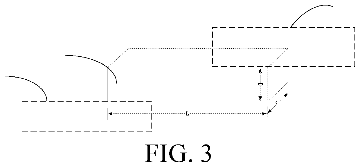

Image

  • Array substrate and display device thereof
  • Array substrate and display device thereof

Examples


Embodiment Construction

[0026]The technical solutions in the embodiments of the present application will be described clearly and completely with reference to the drawings in the embodiments of the present application. Obviously, the described embodiments are only a part of the embodiments, but not all the embodiments. Based on the embodiments of the present application, all other embodiments obtained by those skilled in the art without making creative work fall within the protection scope of the present application.

[0027]In the description of this application, it should be understood that the orientations or positional relationships indicated by the terms “center”, “longitudinal”, “transverse”, “length”, “width”, “thickness”, “above”, “below”, “front”, “back”, “left”, “right”, “vertical”, “horizontal”, “top”, “bottom”, “inner”, “outer”, “clockwise”, “counterclockwise” etc., are based on those shown in the drawings. It is only for the convenience of describing the present application and simplifying the de...


PUM

PropertyMeasurementUnit
thicknessaaaaaaaaaa
thicknessaaaaaaaaaa
areaaaaaaaaaaa

Abstract

The application provides an array substrate and a display device thereof. The array substrate includes a substrate, a gate layer, a first signal electrode layer, an active layer, and a second signal electrode layer, which are stacked, wherein the first signal electrode layer is patterned to form a first signal electrode, the second signal electrode layer is patterned to form a second signal electrode, the first signal electrode is one of a source or a drain, and the second signal electrode is the other one of the source or the drain.

Description

FIELD OF INVENTION[0001]The present application relates to the field of display, in particular to an array substrate and display device thereof.BACKGROUND OF INVENTION[0002]In current touch panel technology, thin film transistors (TFTs) act as a key device for touch panel display driving, and play an important role in display effect of flat panel displays. TFTs mainly include silicon-based TFTs, organic TFTs, and oxide TFTs. In recent years, metal oxide semiconductor-based TFTs are expected to become next-generation mainstream TFT technology due to their advantages such as relatively high carrier mobility, high light transmittance, and low-temperature process. With electrical performance of oxide TFTs continuously improving, their applications are continuously expanding. However, in current metal oxide semiconductor TFT technology, an active layer channel adopts a horizontal channel structure, and a length of the horizontal channel is not easy to control. Such devices adopting horiz...

Claims


Application Information

Patent Timeline
Patent Type & Authority Applications(United States)
IPC IPC(8): H01L27/12
CPCH01L27/124H01L27/1244H01L27/1248H01L29/7869H01L29/41733
Inventor LIU, JUNZHENG
Owner SHENZHEN CHINA STAR OPTOELECTRONICS SEMICON DISPLAY TECH CO LTD
Learn More