Turbine blades including aero-brake features and methods for using the same

a technology of turbine blades and aero-brakes, which is applied in the manufacture of engines, machines/engines, mechanical apparatus, etc., can solve the problems of affecting the gas flow through the turbine engine, and the aero-brake feature may introduce localized aerodynamic losses, so as to reduce the likelihood of rotor whirl, reduce the probability of uneven gas flow, and reduce the effect of uneven force acting

Pending Publication Date: 2022-03-31
GE AVIO
View PDF14 Cites 0 Cited by
  • Summary
  • Abstract
  • Description
  • Claims
  • Application Information

AI Technical Summary

Benefits of technology

The patent relates to improved turbine engines that can reduce uneven flow of gas over the turbine blades resulting from a misaligned rotor assembly with the outer shell. The invention introduces a turbine blade with an aero-brake feature that is selectively exposed to gas flowing through the turbine engine. By disrupting the axial gas flow with the aero-brake feature, localized aerodynamic losses are offset, reducing uneven forces acting on the turbine blades and reducing the likelihood of inducing rotor whirl. In summary, the technical effect of the patent is to improve the efficiency and reliability of turbine engines by reducing uneven flow of gas over the turbine blades.

Problems solved by technology

For example, in some embodiments, the aero-brake feature is exposed to axial gas flow at rotational positions in which the turbine blade is closest to the outer shell, partially disrupting the gas flow through the turbine engine.
By selectively exposing the aero-brake feature and selectively disrupting the axial gas flow, the aero-brake feature may introduce localized aerodynamic losses at discrete rotational positions.

Method used


Image

  • Turbine blades including aero-brake features and methods for using the same
  • Turbine blades including aero-brake features and methods for using the same
  • Turbine blades including aero-brake features and methods for using the same

Examples


Embodiment Construction

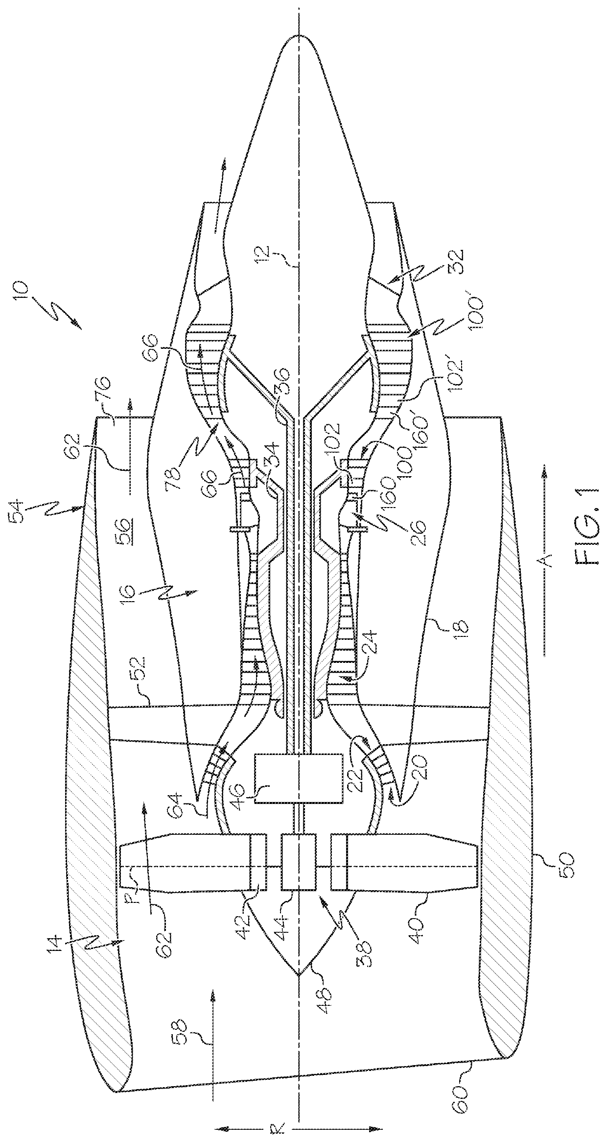
[0024]Embodiments of the present disclosure are directed to turbine blades including an aero-brake feature that is selectively exposed to gas flowing through the turbine engine. For example, in some embodiments, the aero-brake feature is exposed to axial gas flow at rotational positions in which the turbine blade is closest to the outer shell, partially disrupting the gas flow through the turbine engine. The aero-brake feature may be positioned inward of a stator at rotational positions at which the turbine blade is furthest from the outer shell. By selectively exposing the aero-brake feature and selectively disrupting the axial gas flow, the aero-brake feature may introduce localized aerodynamic losses at discrete rotational positions. The localized aerodynamic losses may offset the uneven flow of the gas, thereby reducing uneven forces acting on the turbine blades and reducing the likelihood of inducing rotor whirl. These and other embodiments will now be described with reference ...


PUM


Abstract

A turbine blade including an airfoil portion extending between a leading edge and a trailing edge, a base portion positioned below the airfoil portion, the base portion including an outwardly-extending wing positioned below the airfoil portion, and an aero-brake feature positioned between the outwardly-extending wing and the airfoil portion and extending outward from the base portion, where the aero-brake feature is structurally configured to disrupt axial airflow across the turbine blade.

Description

CROSS REFERENCE TO RELATED APPLICATIONS[0001]The present application claims the benefit of Italian Patent Application No. 102020000018631, filed on Jul. 30, 2020, which is hereby incorporated by reference herein in its entirety.BACKGROUNDField[0002]The present disclosure relates to turbine rotors. More particularly, the present disclosure relates to aerodynamic forces inducing an imbalance in a turbine rotor.Technical Background[0003]Turbine engines are utilized for a variety of applications. For example, turbine engines can be used to drive a generator to produce electrical power, and can be used to provide propulsion to a vehicle, such as an aircraft. Turbine engines generally include a turbine assembly including a turbine shaft and turbine blades that convert axial motion of a gas flowing through the turbine engine into rotational movement of the turbine shaft. The rotor assembly is positioned within an outer shell that at least partially encloses the turbine assembly. However, r...

Claims


Application Information

Patent Timeline
Patent Type & Authority Applications(United States)
IPC IPC(8): F01D5/18F01D5/14
CPCF01D5/187F01D5/143F05D2260/22141F05D2240/307F05D2250/185F05D2260/2212F01D5/147F01D5/16F01D5/145F01D11/001F05D2240/126F05D2240/129F05D2250/184Y02T50/60
Inventor AIRAUDO, MASSIMILIANOCALZA, PAOLOBERTINI, FRANCESCOUSSEGLIO, MATTEO RENATOLIZZER, CRISTIANSOZIO, ERNESTOFURFARO, MATTEOTHIENE, MARCO
Owner GE AVIO
Why Eureka
Try Eureka