Heat dissipating structure and battery provided with the same

a heat dissipating structure and battery technology, applied in the direction of batteries, semiconductor/solid-state device details, electrical devices, etc., can solve the problems of increasing the cost of the circuit board, and increasing the integration of small electronic components on the circuit board. , to achieve the effect of excellent heat dissipation efficiency, elastic deformation, and light weigh

Pending Publication Date: 2022-03-24
SHIN-ETSU POLYMER CO LTD
View PDF0 Cites 0 Cited by
  • Summary
  • Abstract
  • Description
  • Claims
  • Application Information

AI Technical Summary

Benefits of technology

The present invention is a heat dissipating structure that can be used with different types of heat sources. It is lightweight, efficient at dissipating heat, flexible, and can withstand pressure from the heat source without breaking. This invention is suitable for use in batteries with heat dissipating needs.

Problems solved by technology

A control system of automobiles, aircrafts, ships or electronic devices for home use or business use has become further complicated and highly accurate, and correspondingly the integration of small electronic components on a circuit board has been increasingly densified.
Above all, the method of forming the circuit board itself using the material excellent in heat dissipation, for example, diamond, aluminum nitride (AlN), cubic boron nitride (cBN) or the like extremely increases the cost of the circuit board.
Additionally, placement of the cooling fan causes problems of malfunction of a fan as the rotator, need of maintenance for preventing the malfunction, and difficulty in securing a mount space.
Particularly, technological development for enhancing a charging-discharging function of a lithium automobile battery is an important issue.
It is well known that automobile batteries cannot sufficiently exert charging-discharging functions under a high temperature of 60° C. or higher.
Therefore, as with the aforementioned circuit board, heat dissipating enhancement is regarded as an important issue for the battery.

Method used


Image

  • Heat dissipating structure and battery provided with the same
  • Heat dissipating structure and battery provided with the same
  • Heat dissipating structure and battery provided with the same

Examples


first embodiment

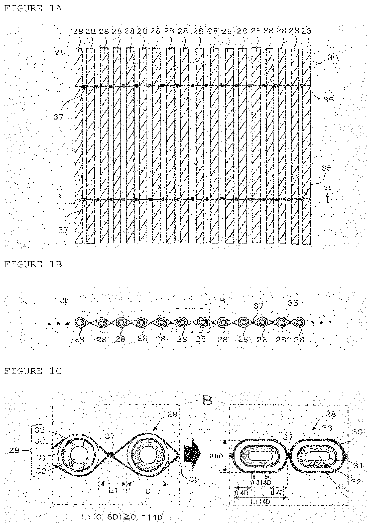
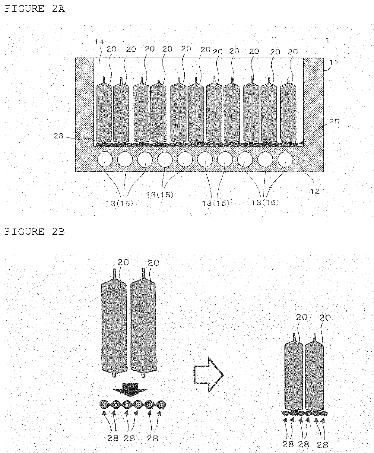
[0031]FIG. 1A is a plan view of a heat dissipating structure according to a first embodiment, FIG. 1B is a sectional view taken along line A-A of FIG. 1A, and FIG. 1C is an enlarged view of a region B of FIG. 1B. FIG. 2A is a longitudinal sectional view of the heat dissipating structure according to the first embodiment, and a battery having the heat dissipating structure. FIG. 2B is a sectional view illustrating change in formation of the heat dissipating structure before and after it is compressed by battery cells as shown in FIG. 2A.

[0032]As illustrated in FIG. 2A, a battery 1 is structured to have a plurality of battery cells 20 in a housing 11 in contact with cooling agent 15. Preferably, a heat dissipating structure 25 is provided between the battery cells 20 as heat sources at proximal ends (lower ends) closer to the cooling agent 15, and a part (bottom 12) of the housing 11 at a side closer to the cooling agent 15. As illustrated, the heat dissipating structure 25 accommodat...

second embodiment

[0055]A heat dissipating structure according to a second embodiment, and a battery having the heat dissipating structure are described. Portions common with those of the embodiment are denoted by the same reference numerals, and redundant description is omitted.

[0056]FIG. 4A is a plan view of the heat dissipating structure according to the second embodiment, FIG. 4B is a sectional view taken along line C-C of FIG. 4A, and FIG. 4C is an enlarged view of a region D of FIG. 4B. FIG. 5A illustrates the heat dissipating structure according to the second embodiment, and FIG. 5B is a sectional view illustrating change in formation of the heat dissipating structure before and after it is compressed by battery cells in FIG. 5A.

[0057]Unlike the battery 1 of the first embodiment, a battery la according to the second embodiment comprises a heat dissipating structure 25a having the multiple heat dissipating members 28 connected by a connection member 35a. Structures of this embodiment besides th...

third embodiment

[0060]A heat dissipating structure according to a third embodiment and a battery provided with the heat dissipating structure are described. Portions common with those of the embodiments are denoted by the same reference numerals, and redundant description is omitted.

[0061]FIG. 6 is a longitudinal sectional view of a heat dissipating structure according to a third embodiment, and a battery having the heat dissipating structure. FIG. 7A shows a part of a process of forming the heat dissipating structure of FIG. 6, and FIG. 7B is a plan view of the heat dissipating structure formed by the process as illustrated in FIG. 7A.

[0062]A battery 1b according to the third embodiment comprises a heat dissipating structure 25b different from the heat dissipating structure 25 disposed in the battery 1 according to the first embodiment, and has the other structure common with the battery 1. The heat dissipating structure 25b used in this embodiment is formed by connecting a plurality of heat dissi...


PUM

PropertyMeasurementUnit
temperatureaaaaaaaaaa
thicknessaaaaaaaaaa
thicknessaaaaaaaaaa

Abstract

In a heat, dissipating structure, a plurality of heat dissipating members for a heat source are connected. Each heat dissipating member has a heat conduction sheet that extends while winding in a spiral shape for conducting the heat from the heat source; a cushion member which is provided on an annular rear side of the heat conduction sheet and can be more easily deformed corresponding to the outer surface shape of the heat source than the heat conduction sheet; an adhesive layer that fixes the heat conduction sheet and the cushion member and is more easily deformed than the heat conduction sheet; and a through passage penetrating in the direction in which the heat conduction sheet extends while being wound. The heat dissipating members are connected by connection members in a state of being aligned perpendicular to the direction in which the heat conduction sheet extends while being wound.

Description

CROSS REFERENCE[0001]The present application is a National Phase of International Application Number PCT / JP2020 / 001886, filed Jan. 21, 2020, and claims priority from Japanese patent application JP2019-020229 filed on Feb. 7, 2019, the content of which is hereby incorporated by reference into this application. Contents of patents, patent applications, and documents cited herein are incorporated by reference into this application.TECHNICAL FIELD[0002]The present invention relates to a heat dissipating structure and a battery provided with the same.BACKGROUND ART[0003]A control system of automobiles, aircrafts, ships or electronic devices for home use or business use has become further complicated and highly accurate, and correspondingly the integration of small electronic components on a circuit board has been increasingly densified. As a result, it is strongly requested to solve malfunction or shortening of service life of the electronic components owing to heat generated in the peri...

Claims


Application Information

Patent Timeline
Patent Type & Authority Applications(United States)
IPC IPC(8): H01M10/6556H01M10/613H01M10/0525H01M10/653H01M10/625H01M50/204H01M50/224H01M50/242
CPCH01M10/6556H01M10/613H01M2220/20H01M10/653H01M10/625H01M10/0525Y02E60/10H01M10/651H01L23/36H01M10/6567H01M50/204H01M50/224H01M50/242H01M10/6554H01M10/6568H01L23/367H01M10/655
Inventor SHIMIZU, TAKAO
Owner SHIN-ETSU POLYMER CO LTD
Why Eureka
Try Eureka