Power amplifier circuit
a power amplifier and circuit technology, applied in the direction of rf amplifiers, amplifiers with semiconductor devices/discharge tubes, high-frequency amplifiers, etc., can solve the problems of large degradation of the overall power efficiency of the amplifier circuit, increase in power loss, and reduce power efficiency, so as to achieve suppress the effect of power efficiency degradation
- Summary
- Abstract
- Description
- Claims
- Application Information
AI Technical Summary
Benefits of technology
Problems solved by technology
Method used
Image
Examples
second embodiment
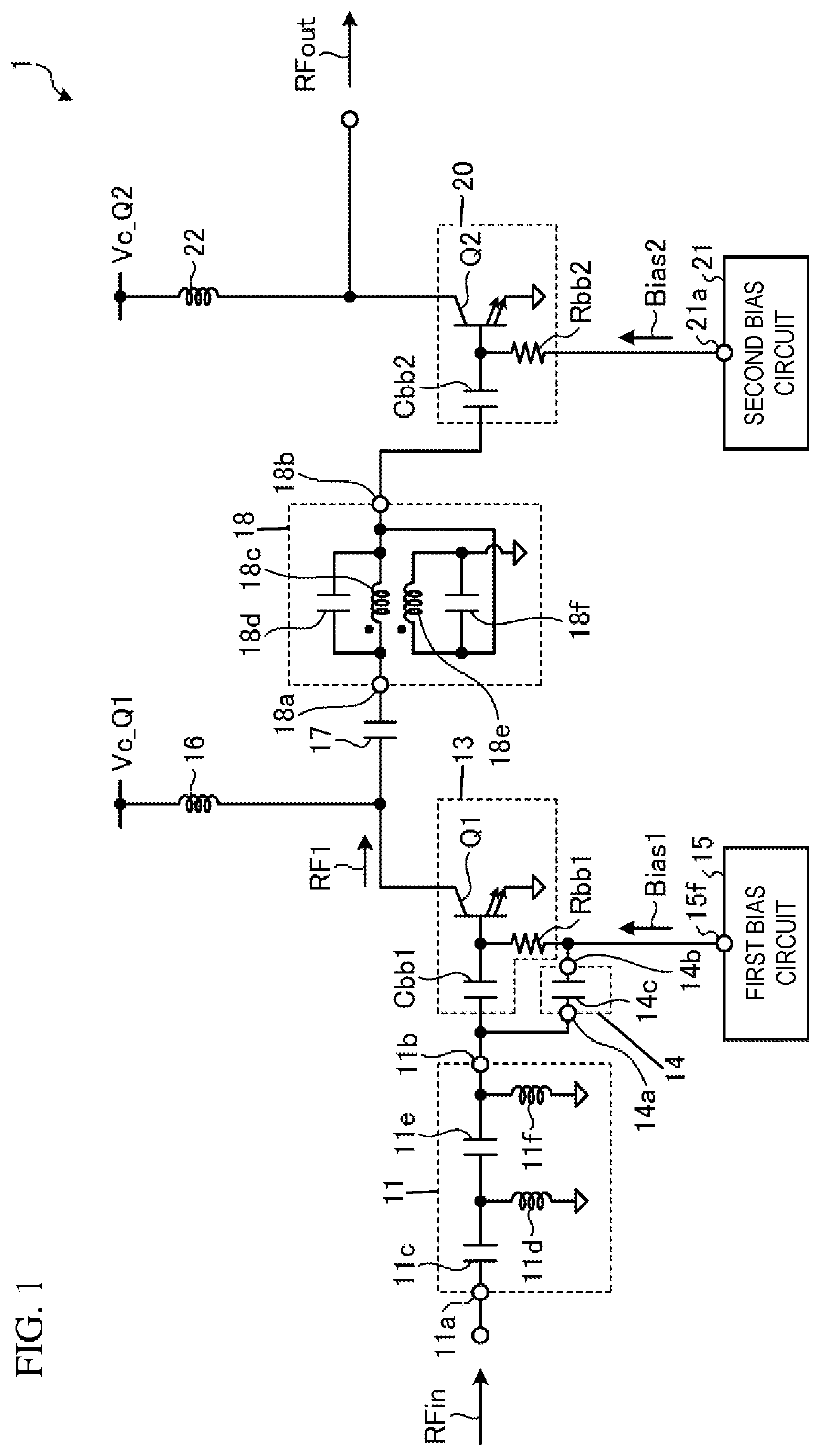
[0113]The automatic transformer 18 is the inter-stage matching circuit between the first amplifier 13 and the second amplifier 20 in the first embodiment, but the present disclosure is not limited to this. Any matching circuit may be employed as the inter-stage matching circuit as long as the matching circuit is a wideband and low-loss matching circuit.
[0114]FIG. 18 illustrates the configuration of an inter-stage matching circuit according to a second embodiment. The inter-stage matching circuit illustrated in FIG. 18 is a transmission line transformer (TLT).
[0115]A transmission line transformer 18A includes a capacitor 18g, a first line 18h, and a second line 18i.
[0116]One end of the capacitor 18g is electrically connected with one end 18a of the transmission line transformer 18A. The other end of the capacitor 18g is electrically connected with one end of the first line 18h. The other end of the first line 18h is electrically connected with the other end 18b of the transmission l...
third embodiment
[0118]FIG. 19 illustrates the configuration of an inter-stage matching circuit according to a third embodiment. The inter-stage matching circuit illustrated in FIG. 19 is a conventional transformer 18B.
[0119]The conventional transformer 18B includes a capacitor 18j, a primary winding 18k, and a secondary winding 18l. The conventional transformer 18B is a transformer that magnetically couples the primary winding 18k and the secondary winding 18l, whose winding ratio is 1:n, with each other so as to realize impedance conversion at a conversion ratio of 1:n{circumflex over ( )}2.
[0120]One end of the capacitor 18j is electrically connected with one end 18a of the conventional transformer 18B. The other end of the capacitor 18j is electrically connected with one end of the primary winding 18k. The other end of the primary winding 18k is electrically connected with a reference potential. One end of the secondary winding 18l is electrically connected with the other end 18b of the conventio...
fourth embodiment
[0122]The impedance circuit 14 includes the capacitor 14c in the first embodiment, but the present disclosure is not limited to this. Any circuit may be employed as the impedance circuit 14 as long as the circuit is able to block DC components of the high frequency input signal RFin after passing through the high pass filter 11 and pass AC components of the same.
[0123]FIG. 20 illustrates the configuration of an impedance circuit according to a fourth embodiment.
[0124]An impedance circuit 14A includes a capacitor 14d and an inductor 14e. One end of the capacitor 14d is electrically connected with one end 14a of the impedance circuit 14A. The other end of the capacitor 14d is electrically connected with one end of the inductor 14e. That is, the capacitor 14d and the inductor 14e are LC-connected in series. The other end of the inductor 14e is electrically connected with the other end 14b of the impedance circuit 14A. Here, one end of the capacitor 14d may be electrically connected wit...
PUM
 Abstract
Description
Claims
Application Information
 - R&D
- Intellectual Property
- Life Sciences
- Materials
- Tech Scout
- Unparalleled Data Quality
- Higher Quality Content
- 60% Fewer Hallucinations
Browse by: Latest US Patents, China's latest patents, Technical Efficacy Thesaurus, Application Domain, Technology Topic, Popular Technical Reports.
© 2025 PatSnap. All rights reserved.Legal|Privacy policy|Modern Slavery Act Transparency Statement|Sitemap|About US| Contact US: help@patsnap.com


