
Coil unit and contactless power supplying apparatus

Active Publication Date: 2016-01-07
YAZAKI CORP
View PDF4 Cites 6 Cited by
  • Summary
  • Abstract
  • Description
  • Claims
  • Application Information

AI Technical Summary

Benefits of technology

The present invention provides a new design for a core in a coil that reduces the leakage of magnetic flux and improves power efficiency. The core is divided into a center portion and two end portions with protrusion portions that face another coil. This design makes it easier to manufacture the core and allows for adjustment of the magnetic field distribution even when the coil is inclined. Additionally, the invention allows for easier adjustment of the protrusion amounts to achieve the desired magnetic field distribution.

Problems solved by technology

Therefore, there have been problems that, when the vehicle is not accurately stopped at a predetermined power supplying position, position displacement occurs between the power supplying side resonant coil and the power receiving side resonant coil, and then a leakage magnetic field is generated and a decrease in power efficiency occurs.
However, in conventional techniques, it could not have been said that an increase in the leakage magnetic flux to the position displacement and the decrease in power efficiency can be sufficiently reduced.

Method used


Image

  • Coil unit and contactless power supplying apparatus
  • Coil unit and contactless power supplying apparatus
  • Coil unit and contactless power supplying apparatus

Examples


Embodiment Construction

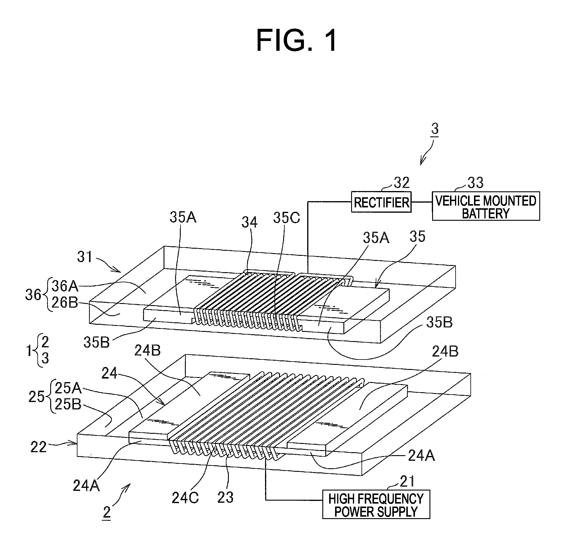
[0019]Hereinafter, a power supplying system of the present invention will be described with reference to FIG. 1 to FIG. 3. As illustrated in FIG. 1, a contactless power supplying apparatus 1 includes a power supplying unit 2 provided in a power supplying facility, and a power receiving unit 3 mounted on a vehicle.

[0020]The power supplying unit 2, as illustrated in FIG. 1, includes a high frequency power supply 21 as a power supply, and a power supplying side coil unit 22 (coil unit) to which high frequency power from the high frequency power supply 21 is supplied.

[0021]The high frequency power supply 21 generates the high frequency power to supply the power to a power supplying side resonant coil 23 to be described later of the power supplying side coil unit 22. The high frequency power to be generated by the high frequency power supply 21 is provided so that the frequency is equal to a resonant frequency (for example, 13.56 MHz) of the power supplying side resonant coil 23 and the ...


PUM


Abstract

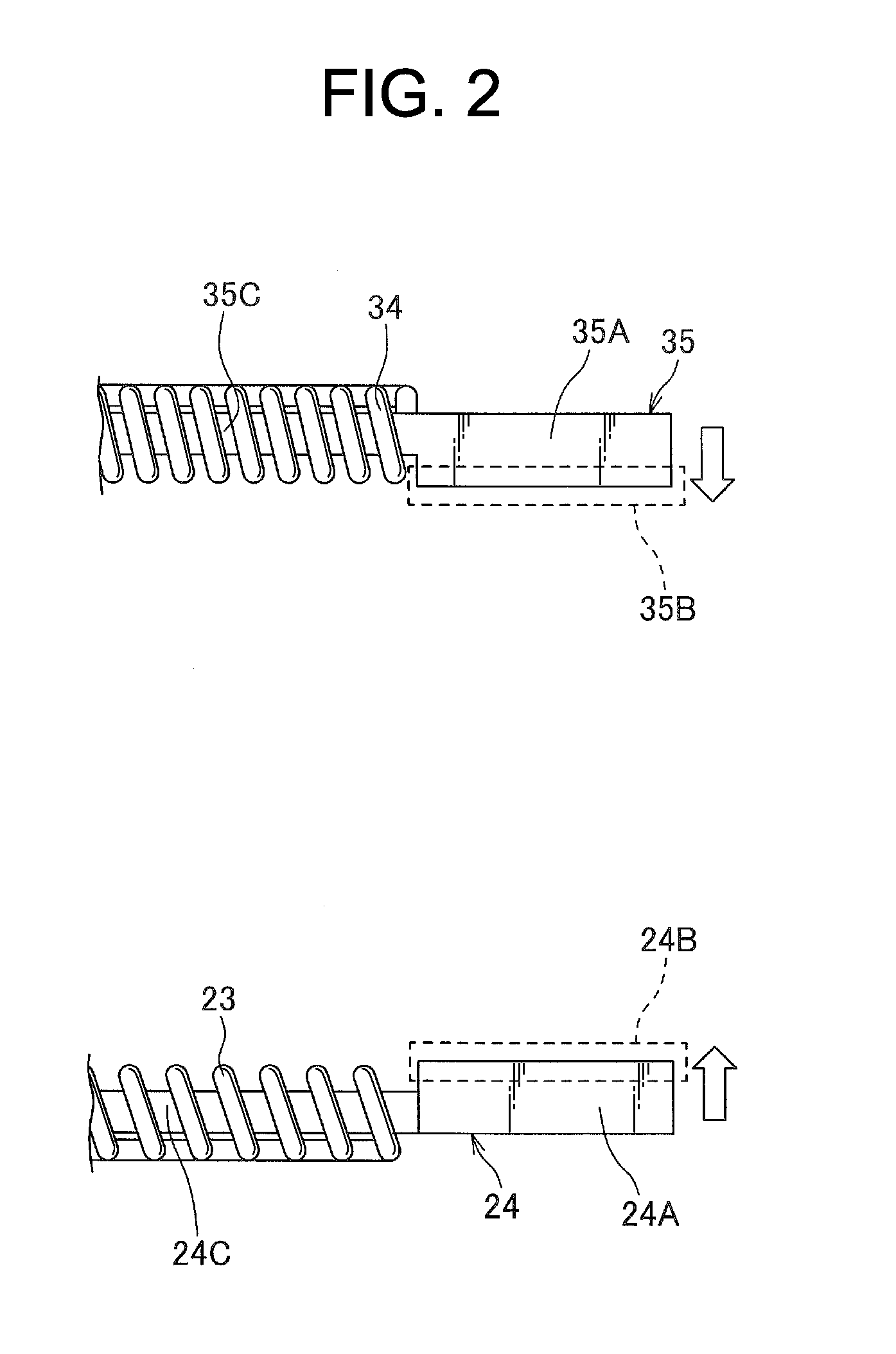
In a power supplying side core around which a power supplying side resonant coil is wound that contactlessly supplies power to a power receiving side resonant coil, a pair of protrusion portions is provided that protrudes from central axis direction both sides of the power supplying side resonant coil toward the power receiving side resonant coil. Further, in a power receiving side core around which the power receiving side resonant coil is wound that contactlessly receives power from the power supplying side resonant coil, a pair of protrusion portions is provided that protrudes from central axis direction both sides of the power receiving side resonant coil toward the power supplying side resonant coil.

Description

TECHNICAL FIELD[0001]The present invention relates to a coil unit and a contactless power supplying apparatus, especially, a coil unit that performs contactless power supplying and a contactless power supplying apparatus that includes the coil unit.BACKGROUND OF THE INVENTION[0002]In recent years, as a power supplying system for supplying power to a battery mounted on a hybrid vehicle and an electric vehicle, wireless power supplying has been focused that does not use a power supply cord and a power transmission cable (Patent Literatures 1 to 3). As one of the wireless power supplying technique, that of a resonant type has been known. In the resonant type contactless power supplying apparatus, one of a pair of resonant coils electromagnetically resonant with each other is installed on the ground of a power supplying facility and the other is mounted on a vehicle, and power is contactlessly supplied from the resonant coil installed on the ground of the power supplying facility to the...

Claims


Application Information

Patent Timeline
IPC IPC(8): H01F27/34B60L5/00B60M7/00H01F27/24H01F38/14
CPCH01F27/346H01F27/24H01F38/14Y02T10/70Y02T10/7072Y02T90/14H01F5/00H01F27/00H01F27/02H01F27/06H01F27/08
Inventor TERAYAMA, HAJIMEKAGAMI, KAZUYOSHITANAKA, SHINGO
Owner YAZAKI CORP
Learn More