
Coated cutting tool

Active Publication Date: 2022-02-10
TUNGALOY CORP
View PDF0 Cites 0 Cited by
  • Summary
  • Abstract
  • Description
  • Claims
  • Application Information

AI Technical Summary

Benefits of technology

The invention offers a coated cutting tool that is more durable and resistant to wear and fracture, leading to a longer lifespan for the tool.

Problems solved by technology

Since the layer of PTL 1 has a grain size of more than 200 nm as a whole, it is expected that while exhibiting excellent wear resistance, sudden fractures and chipping are likely to occur.
The coated cutting tool of PTL 2 has columnar crystals forming the layer A and the granular crystals forming the layer B, which have the same composition, alternately laminated, and since the coated cutting tool has high interfacial consistency, the distortion is small and the hardness of the layer is not sufficient.
As a result, it is difficult to extend the tool life due to insufficient wear resistance.

Method used


Image

  • Coated cutting tool

Examples


example 1

[0100]As a substrate, an insert of CNMG120408-SM (cemented carbide having a composition of 89.6WC-9.8Co-0.6Cr3C2 (mass %)) was prepared. A TiC evaporation source and a metal evaporation source were disposed in a reaction vessel of an arc ion plating device so as to have a composition of each layer shown in Tables 1 and 2. The prepared substrate was fixed to a fixing bracket of a rotary table in the reaction vessel.

[0101]Then, the inside of the reaction vessel was evacuated until a pressure was a vacuum of 5.0×10⁻³ Pa or less. After evacuation, the substrate was heated to a temperature of 450° C. by a heater in the reaction vessel. After heating, Ar gas was introduced into the reaction vessel to make the pressure to 2.7 Pa.

[0102]In an Ar gas atmosphere with a pressure of 2.7 Pa, a bias voltage of −400 V to was applied to the substrate, a current of 40 A was flowed through a tungsten filament in the reaction vessel, and a surface of the substrate was subjected to an ion bombardment tr...


PUM

PropertyMeasurementUnit
Grain sizeaaaaaaaaaa

Abstract

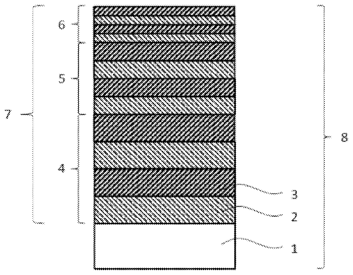
Provided is a coated cutting tool having improved wear resistance and fracture resistance and a long tool life. The coated cutting tool includes a substrate, and a coating layer formed on a surface of the substrate. The coating layer has a laminated structure in which a first layer and a second layer are alternately laminated for one or more layers. The first layer is a compound layer having a composition represented by Ti(CxN1-x). The second layer is a compound layer having a composition represented by (TiyAl1-y)N. The laminated structure includes first to third laminated structures in this order from a substrate side to a surface side of the coating layer. An average thickness per layer of each of the first layer and the second layer in the first to third laminated structures is in a specific range. An average thickness of the first to third laminated structures is in a specific range.

Description

CROSS-REFERENCES TO RELATED APPLICATIONS[0001]This application relates to and claims priority from Japanese Patent Application No. 2020-134827 on (Aug. 7, 2020), the entire disclosure of which is incorporated herein by reference.BACKGROUND OF THE INVENTIONField of the Invention[0002]The present invention relates to a coated cutting tool.Description of Related Art[0003]In the related art, cutting tools made of cemented carbide or cubic boron nitride (cBN) sintered body have been widely used for cutting steel or the like. Among them, surface coated cutting tools containing one or two or more hard coating films such as a TiN layer and a TiAlN layer on a surface of a cemented carbide substrate are used for various processing due to high versatility thereof.[0004]For example, WO 2014 / 136755 (PTL 1) proposes a layer represented by (AlaTibMc)X (wherein M represents at least one element selected from the group consisting of Zr, Hf, V, Nb, Ta, Cr, Mo, W, Y, B, and Si, X represents at least o...

Claims


Application Information

Patent Timeline
IPC IPC(8): B23B27/14C23C28/04C23C14/32C23C14/30C23C14/06
CPCB23B27/148C23C28/044C23C14/32B23B2228/10C23C14/0664C23C14/0641C23C14/30B23D79/00C23C28/42C23C28/44C23C30/005B23B2224/24B23C5/16
Inventor KATAGIRI, TAKAO
Owner TUNGALOY CORP
Learn More