
Device for characterising a liquid material

a liquid material and device technology, applied in the direction of rotary stirring mixers, instruments, transportation and packaging, etc., can solve the problems of affecting the life and thus the efficiency of photovoltaic cells, the conventional method of material analysis is not entirely satisfactory, and the inability to continuously control the purity of molten metal

Pending Publication Date: 2022-01-27
COMMISSARIAT A LENERGIE ATOMIQUE ET AUX ENERGIES ALTERNATIVES
View PDF3 Cites 0 Cited by
  • Summary
  • Abstract
  • Description
  • Claims
  • Application Information

AI Technical Summary

Benefits of technology

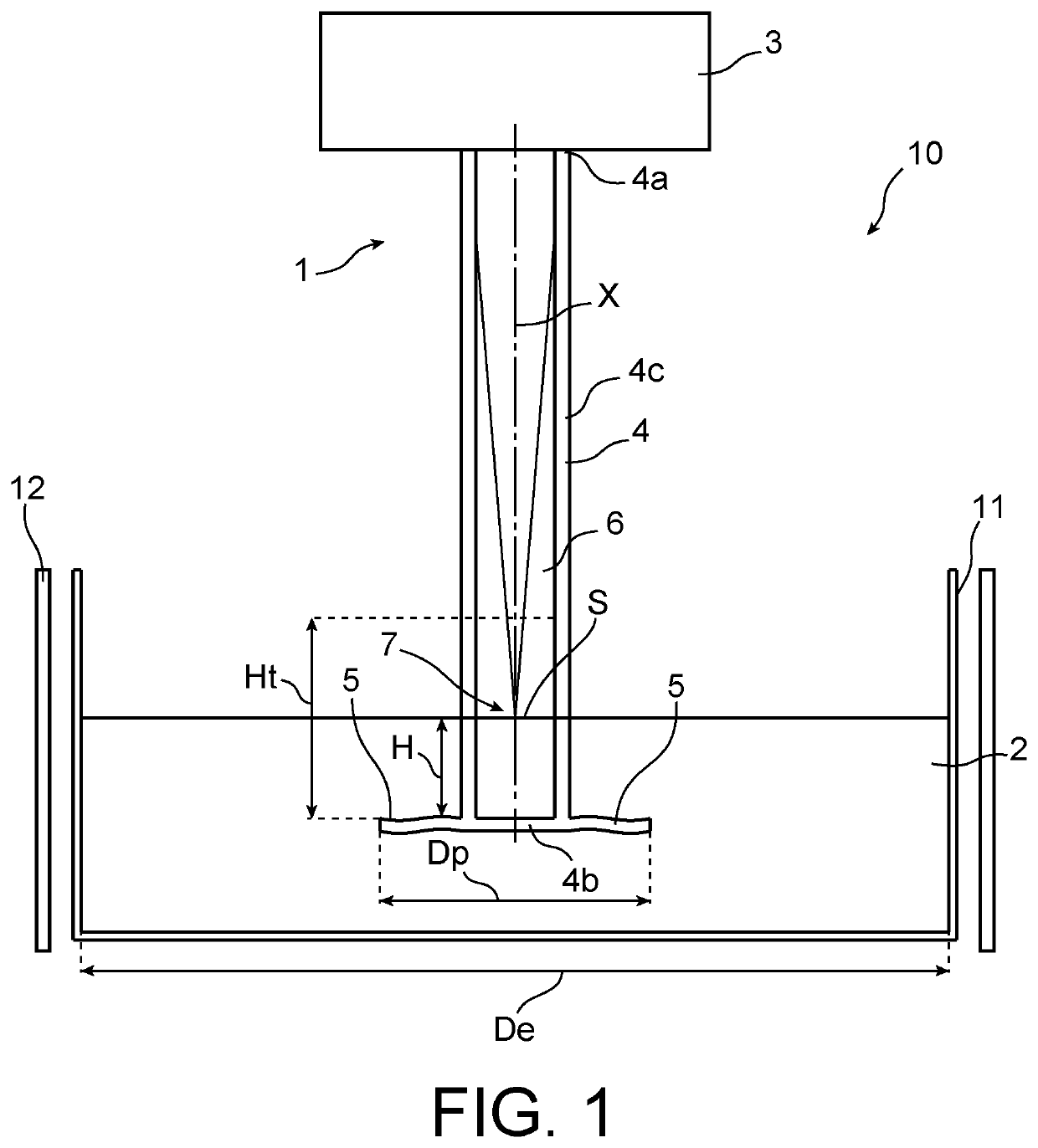
The patent proposes an online device for characterizing liquid materials, especially molten metals, using LIBS technology. The device has a stirring system with a stationary analysis surface that can be easily replaced and is representative of the melt or volume. It has orifices to allow excess liquid material to flow out and stabilize the analysis surface. This device can simplify the analysis, reduce time, costs, and ensure high-quality monitoring of materials.

Problems solved by technology

However, the presence of a high level of impurities in the liquid metallic silicon is harmful for the photoelectric effect because it favours the recombination of charge carriers, which influences their lifetime and thus the efficiency of the photovoltaic cells.
Nevertheless, this conventional procedure for analysing the material is not entirely satisfactory, and in particular is not suitable for the continuous control of the purity of the molten metal, because it requires prior steps of preparation of samples, which require time and have high costs.
In addition, since the LIBS technique makes it possible to carry out remote analysis, it proves to be particularly suited for the analysis of materials in the molten state at high temperature, and notably for the analysis of molten silicon, and the analysis of materials not being able to be handled because representing a potential hazard.
However, at larger scale, this measurement method may have a drawback linked to the fact that, in the case of molten metals, the chemical composition of the analysed surface is not generally representative of the composition of the overall volume of the metal.
Indeed, due to the high reactivity of molten metals, and for example silicon, the material present at the interface with the atmosphere generally undergoes oxidation or nitridation phenomena which lead to the generation of surface slags.
Due to the segregation of the various impurities between the molten metal and the oxidised phase, the slag generally does not have the same composition as the metal, which thus calls into question the reliability of measurements made with this method.
Nevertheless, this device is not satisfactory in that it notably has the drawback of limiting the analysis to materials with low melting points, typically of the order of 660° C. for aluminium at atmospheric pressure, whereas silicon, for example, has a melting point in the region of 1412° C. at atmospheric pressure.
This solution has been applied for zinc and aluminium, but it is not efficient for highly oxidisable metals such as silicon or zirconium.
Indeed, in the case of a highly oxidisable metal, surface oxidation can occur with the residual oxygen of the load and make the analysis surface invalid.
However, this solution has the major drawback of instability of the surface to analyse which is intimately linked to the dynamic of the generated bubble.
However, this solution has been tested on pilot furnaces and remains difficult to apply to industrial capacity furnaces because it uses a set of mirrors of which the adjustment is very specialised.
The problem resides in the retention of the gas which has a tendency to escape rapidly upwards to return to the atmosphere and the maintaining of the metals which, for their part, conversely, fall easily to the bottom of the melt and agglomerate.
However, the geometry of the blade serves to obtain efficient stirring at low rotation speed and does not guarantee the presence of an analysis zone that is stable, renewable and representative which could be intended to carry out in situ characterisation measurements.
However, they are not intended to be used to guarantee the renewal, the reproducibility and the stability of a surface which may be analysed by an in situ characterisation technique such as for example the LIBS technique.

Method used


Image

  • Device for characterising a liquid material
  • Device for characterising a liquid material

Examples


first embodiment

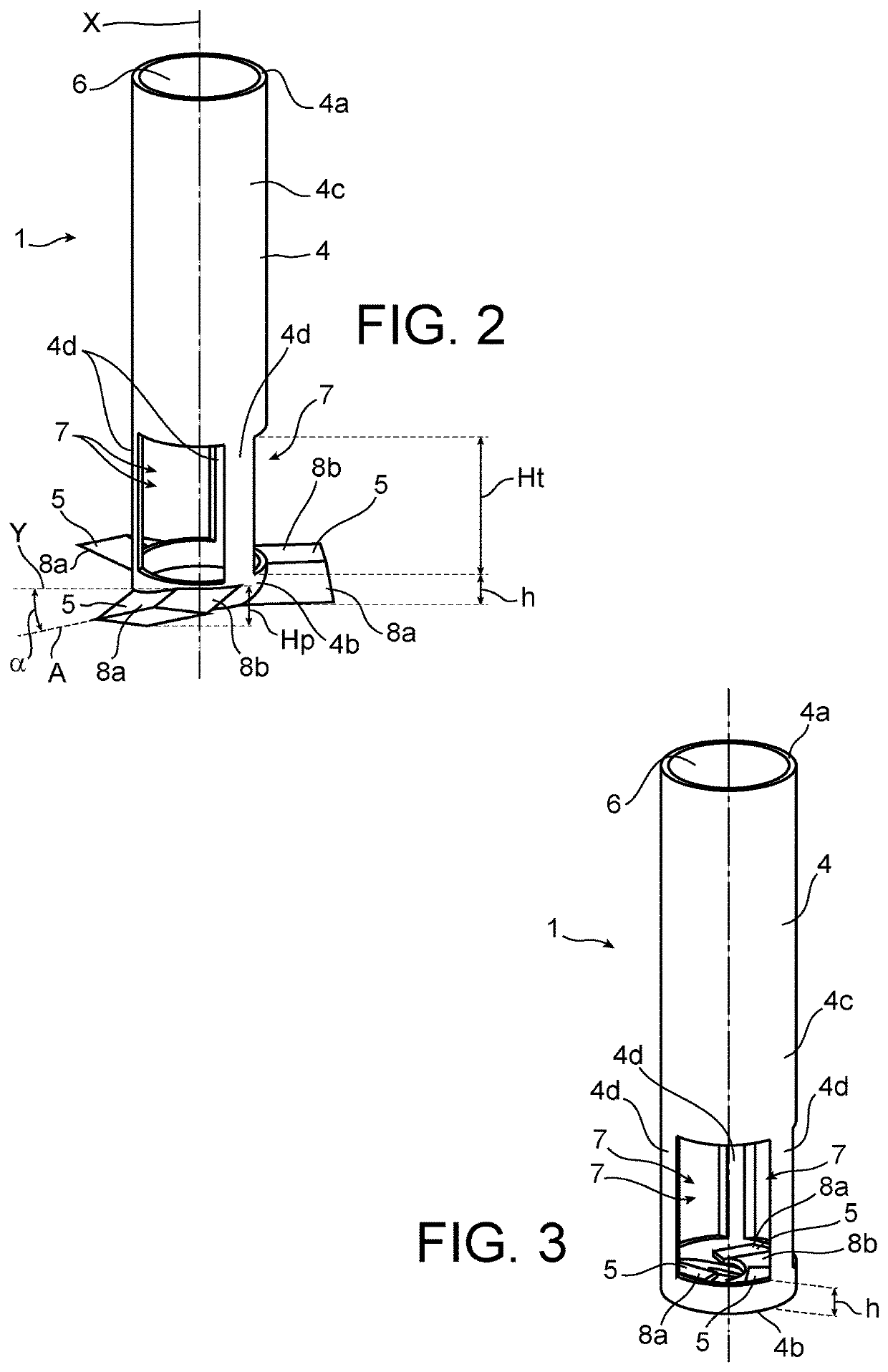
[0108]According to FIG. 2, the external blades 5 make it possible to generate an axial flow, i.e. a vertical movement of the liquid, at the level of the blades 5 outside of the central part 4. The direction of this movement, downwards or upwards, is linked to the direction of rotation. The second hollow end 4b enables a sucking upwards of the liquid, i.e. towards the analysis surface S, and its evacuation by means of orifices 7.

second embodiment

[0109]According to FIG. 3, the inner blades 5 enable, for a rotation in the clockwise direction, the sucking of the liquid through the second hollow end 4b upwards and more precisely towards the free analysis surface S and next its evacuation by means of orifices 7. The flow speed remains constant during stirring.

[0110]Unlike blades of the prior art, the behaviour of the liquid generated by the two shapes of blades of the embodiments of FIGS. 2 and 3 is advantageous and original. In addition to the stirring of the liquid, the second hollow end 4b allows a vertical sucking up of the liquid which is evacuated by means of orifices 7 and thus renews the analysis surface S.

[0111]The number of blades 5 may vary as a function of the desired power and stirring speed, the properties of the liquid and the geometry of the vessel 11.

[0112]The direction of rotation is imposed by the shape of the blades 5, and more precisely the wings 8a, 8b.

[0113]Tests were carried out in a vessel 11 in the for...


PUM


Abstract

A device for characterising at least one liquid material includes an analysis head and a rotating mechanical mixer. The mixer includes a central part having an internal cavity which forms an analysis chamber, a first end connected to the analysis head, and a plurality of stirring blades which are connected to a second end that is hollow so as to ensure fluid communication between the internal cavity and the liquid bath. The mechanical stirring blades are intended to be totally submerged, the central part comprises one or more openings intended to be partially submerged, and each mechanical stirring blade comprises at least one stirring flange oriented at a non-zero angle of orientation.

Description

TECHNICAL FIELD[0001]The present invention pertains to the general field of the characterisation of a liquid material.[0002]It relates to any technique for characterising a liquid material and surface analysis requiring a representative, stable and renewable analysis surface of the liquid. As examples, the invention may be used with spectrometry techniques such as the Inductively Coupled Plasma Mass Spectrometry (ICP-MS) technique and with other surface analysis techniques such as pyrometry. In a preferential manner, the invention is applied to the field of spectral analysis of a liquid material implementing a spectroscopy technique, and notably Laser Induced Breakdown Spectroscopy (LIBS).[0003]The invention may be applied at high temperature or at room temperature. For example, it may be applied to materials at high temperature such as molten metals (aluminium, steel, zinc, sodium, etc.), molten salts, liquid glass in a vitrification furnace, and to liquids at low temperature such ...

Claims


Application Information

Patent Timeline
IPC IPC(8): G01N21/71G01N33/205
CPCG01N21/718B01F7/00291G01N33/205G01N21/8507B01F27/1125G01N2201/0697
Inventor BELRHITI, YOUNÈSALBARIC, MICKAËLBENMANSOUR, MALEKPELLETIER, DAVID
Owner COMMISSARIAT A LENERGIE ATOMIQUE ET AUX ENERGIES ALTERNATIVES
Learn More