Structural body manufacturing method and structural body

a manufacturing method and structural technology, applied in the field of structural body manufacturing method and structural body, can solve the problems of low accuracy, distortion, and inability to obtain flat plate shape, and achieve the effect of low cost and high accuracy of form and strength

Inactive Publication Date: 2022-01-27
GRAPHITE DESIGN
View PDF6 Cites 0 Cited by
  • Summary
  • Abstract
  • Description
  • Claims
  • Application Information

AI Technical Summary

Benefits of technology

[0016]According to the present invention, it is possible to provide a structural body manufacturing method and a structural body that offer high accuracy of form and strength despite being low cost.

Problems solved by technology

However, since the frames of bicycles are originally made of metal round pipes joined together, it is relatively easy to replace them with FRP-made hollow cylindrical members, with the exception of difficulties at the join portions or the like.
On the other hand, with regard to the structural bodies used in vehicles, since the installation space is limited, there is a problem in that it is difficult to use hollow cylindrical members as-is.
However, in a FRP-made structural body formed in this way, there are problems in that distortion is likely to occur in the curing process, and an accurate, flat plate shape cannot be obtained.
For this reason, there is a problem that the adhesive of the sheets peels off at both edges in the central width direction of the structural body, the fibers tend to peel off, and the strength is decreased.
However, when molding is performed by such a manufacturing method, there is a risk that wrinkles, voids, and resin rich caused by reinforcing fibers that cannot conform to the shape change in accordance with the mold may occur when the wall thickness of the prepreg changes during the pressurizing and heating process at the time of molding.
As a result, the product quality and the product strength of the FRP-made structural bodies is decreased.

Method used


Image

  • Structural body manufacturing method and structural body
  • Structural body manufacturing method and structural body
  • Structural body manufacturing method and structural body

Examples


first embodiment

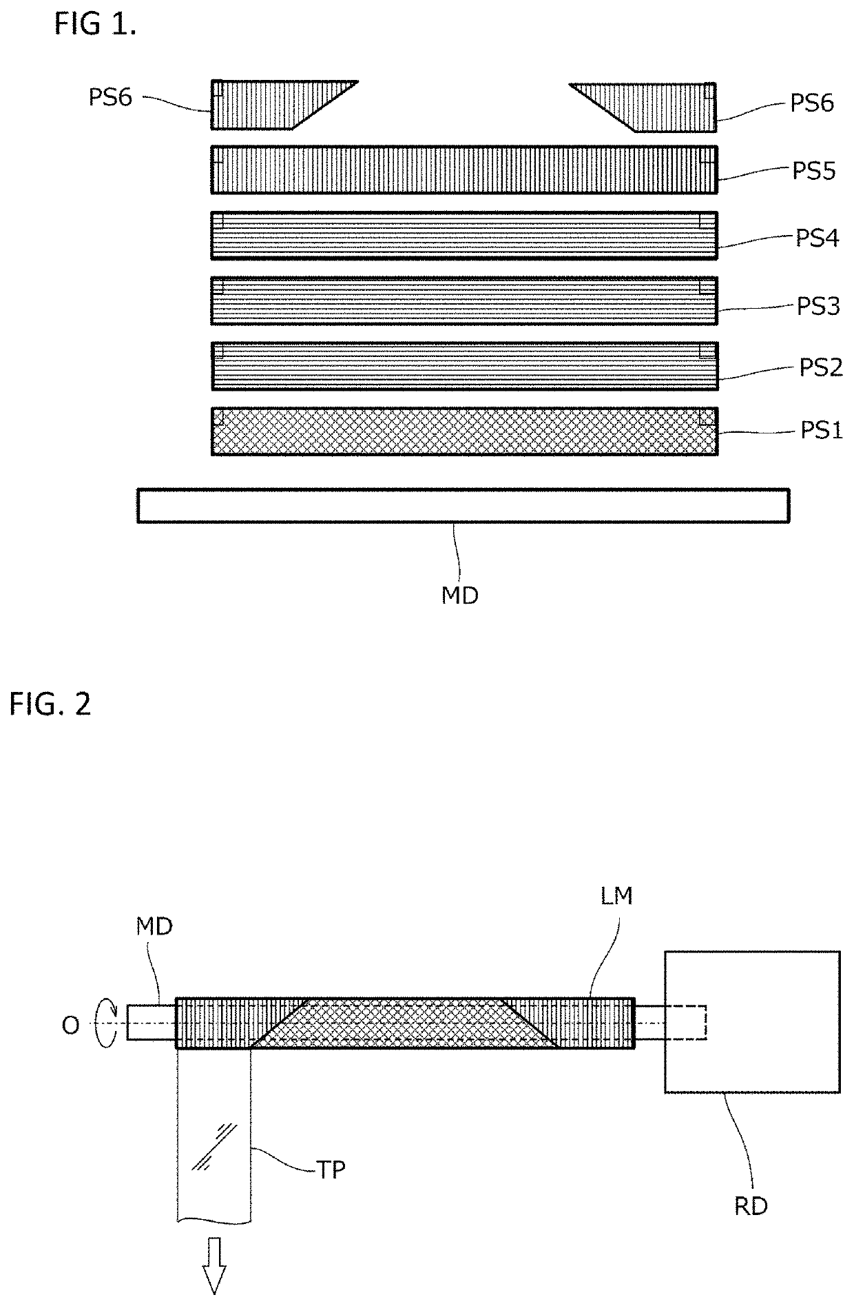
[0044]The structural body manufacturing method according to the first embodiment will be described. FIG. 1 is a diagram schematically illustrating a first step. As illustrated in FIG. 1, a mandrel MD and various prepreg sheets PS1˜PS6 are prepared.

[0045]The outer diameter of the mandrel MD is set to be slightly smaller with respect to the outer circumferential length of the structural body to be finally formed, in consideration of the thickness of the laminate wound on the outside. That is, it is desirable that the outer diameter in a state in which a plurality of prepreg sheets are wound around the mandrel MD substantially matches the design value of the outer peripheral length of the structure to be finally formed.

[0046]With regard to the prepreg sheets PS1˜PS6, here, sheets in which carbon fibers are impregnated into a raw material of an epoxy resin are used. In each prepreg sheet, the carbon fibers are oriented with regularity, and the solid lines in FIG. 1 illustrate the orient...

modified example

[0078]By attaching a mounting member to the structural body ST1 formed as described above, it is possible to connect the structural body ST1 to other components. FIG. 11 is a diagram schematically illustrating a fifth step according to a modified example. Here, a metal mounting member AT or the like is prepared in advance.

[0079]The mounting member AT has a shape in which a tapered plate portion PT is integrally joined to a ring-shaped head RG. Grooves GV are formed in the upper and lower surfaces of the plate portions PT, respectively.

[0080]Referring to FIG. 7, when the laminate body LM is disposed between the upper mold UD and the lower mold LD without interposing a rubber body therein, the plate portions PT of the mounting member AT are opposed at both ends (FIG. 11(a)), and the plate portions PT are inserted into the laminate body LM (FIG. 11(b)).

[0081]Thereafter, as illustrated in FIG. 9, by performing mold clamping of the upper mold and the lower mold, when the laminate body LM...

second embodiment

[0084]A structural body manufacturing method according to a second embodiment will be described. FIG. 13 and FIG. 14 are diagrams schematically illustrating a fifth step according to the second embodiment. In the second embodiment, the first step to the fourth step are the same as in the first embodiment. That is, use of the preform bodies formed in the first to fourth steps can be shared.

(Fifth Step)

[0085]The laminate body LM, which is a preform body formed in the fourth step and from which the mandrel MD was pulled out, is disposed between the plate-shaped upper mold UD and the plate-shaped lower mold LD as illustrated in FIG. 13, without inserting a rubber body or the like.

[0086]Thereafter, the upper mold UD and the lower mold LD are brought relatively close to each other in a parallel state and mold clamping is performed. Since the interior of the laminate body LM has a cavity, as illustrated in FIG. 14, the laminate body LM is crushed by the lower plane of the upper mold UM and...


PUM

PropertyMeasurementUnit
tensionaaaaaaaaaa
temperatureaaaaaaaaaa
exothermic temperatureaaaaaaaaaa

Abstract

A structural body manufacturing method includes a first step of forming a cylindrical laminate body LM by winding a plurality of sheets including reinforcing fibers and an uncured thermosetting resin around a mandrel MD, a second step of compressing an entire circumference of the laminate body with a tape TP, a third step of heating the laminate body to a state prior to when the thermosetting resin is completely cured, a fourth step of extracting the mandrel from the laminate body, a fifth step of placing the laminate body around which the tape is wound in a molding die UD, LD, pressurizing the laminate body, and heating the laminate body until the thermosetting resin is completely cured, and a sixth step of removing the laminate body from the molding die and peeling off the tape.

Description

TECHNICAL FIELD[0001]The present invention relates to a structural body manufacturing method and a structural body.BACKGROUND OF THE INVENTION[0002]From the viewpoint of component weight reduction, there have been attempts to replace metallic structural bodies with structural bodies made of Fiber Reinforced Plastics (FRP), in which reinforcing fibers such as carbon fibers are strengthened by resins. Here, as an example of a FRP-made structural body, the hollow cylindrical members already used for bicycle frames or the like are known.[0003]However, since the frames of bicycles are originally made of metal round pipes joined together, it is relatively easy to replace them with FRP-made hollow cylindrical members, with the exception of difficulties at the join portions or the like. On the other hand, with regard to the structural bodies used in vehicles, since the installation space is limited, there is a problem in that it is difficult to use hollow cylindrical members as-is. Accordin...

Claims


Application Information

Patent Timeline
Patent Type & Authority Applications(United States)
IPC IPC(8): B29C70/32B29C70/34B29C70/54
CPCB29C70/32B29K2101/10B29C70/54B29C70/345B29C70/347B29C70/46B29C70/86B29K2307/04B29L2023/22B29K2105/0881
Inventor MATSUMOTO, KEIZOMATSUZAKI, YUICHIROTSUJIMOTO, RYUTA
Owner GRAPHITE DESIGN
Why Eureka
Try Eureka