optical components

A technology of optical components and mounting parts, which is applied in the field of optical components of vehicle lamps, can solve the problems of increased manufacturing cost and large size of optical components, and achieve the effects of improving rigidity, avoiding deformation, and improving forming accuracy

Active Publication Date: 2014-10-15
KOITO MFG CO LTD
View PDF5 Cites 0 Cited by
  • Summary
  • Abstract
  • Description
  • Claims
  • Application Information

AI Technical Summary

Problems solved by technology

However, such measures for concentrating sunlight are accompanied by problems of increased manufacturing costs and larger sizes of optical components.

Method used


Image

  • optical components
  • optical components
  • optical components

Examples


Embodiment approach 1

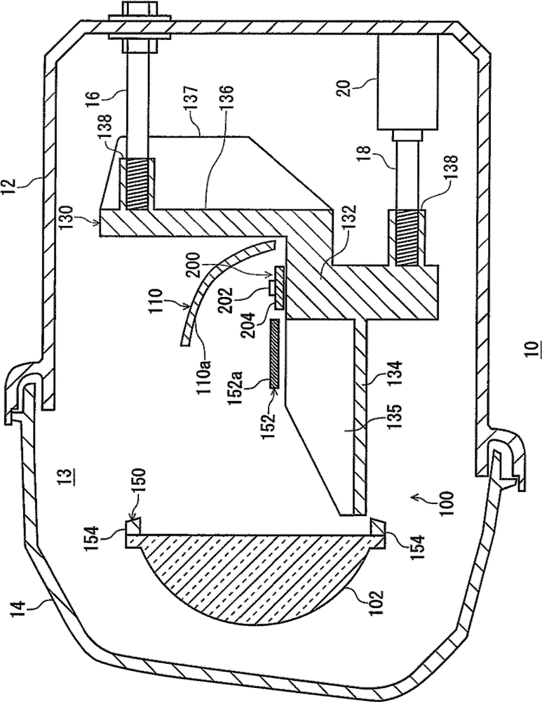
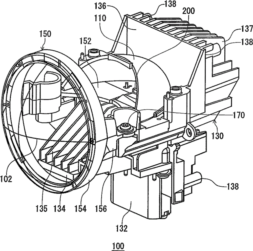
[0049] figure 1 It is a schematic partial cross-sectional view illustrating an internal structure of a vehicle headlamp device as a vehicle lamp including the optical unit of the first embodiment. figure 2 It is a schematic perspective view of the optical unit of Embodiment 1 viewed obliquely from above. In addition, the headlight device for a vehicle has a pair of headlight units formed bilaterally symmetrically. One is located on the right front part of the vehicle. figure 1 Shows the configuration of either one of the left and right headlamp units as a vehicle headlamp device.

[0050] like figure 1 As shown, the vehicle headlamp device 10 of the present embodiment includes a lamp body 12 having an opening on the vehicle front side, and a translucent cover 14 attached to cover the opening of the lamp body 12 . The translucent cover 14 is formed of translucent resin, glass, or the like. An optical assembly 100 is accommodated in a lamp chamber 13 formed by the lamp bod...


PUM


Abstract

An optical assembly, comprising: a heat sink for heat dissipation of a light source; a reflector mounting portion, a lens mounting portion, and a joint portion between the reflector mounting portion and the lens mounting portion, and the light of the light source A base part configured such that the reflector attached to the reflector attachment part reflects and enters the projection lens attached to the lens attachment part. The heat sink is exposed in a space surrounded by the lens mounting part, the coupling part, and the reflector mounting part.

Description

technical field [0001] The present invention relates to optical assemblies, in particular to optical assemblies for vehicle lamps. Background technique [0002] There is known an optical unit used in a vehicle lamp that reflects light from a light source such as a semiconductor light emitting element by a reflector and irradiates it forward of the vehicle through a projection lens. The optical unit has a structure including a heat sink in which a base on which a projection lens and a reflector are mounted is connected to a mounting part having a semiconductor light emitting element. [0003] On the first side of the optical assembly, for example, as shown in FIG. 6 of Japanese Patent Application Laid-Open No. 2007-35547, the cover corresponding to the base part has a planar part arranged substantially horizontally, and a non-shielding cover in front of the planar part. A curved portion that bends downward in such a way that the light from the light source enters the project...

Claims


Application Information

Patent Timeline
Patent Type & Authority Patents(China)
IPC IPC(8): F21V13/00F21V17/12F21W101/02F21W107/10
CPCF21S48/1159B60Q1/076F21S48/155F21S48/1305F21S48/328F21S48/321F21S48/1216F21V13/04B60Q1/0035F21S41/295F21S41/255F21S41/39F21S41/55F21S45/10F21S45/47F21S41/148
Inventor 安田雄治山道龙彦渡边重之
Owner KOITO MFG CO LTD
Why Eureka
Try Eureka