Pressure sensor
a technology of pressure sensor and sensor body, which is applied in the direction of rapid change measurement, instruments, measurement devices, etc., can solve the problems of heat influence that cannot be curbed or prevented, and further degrade the accuracy of the sensor par
- Summary
- Abstract
- Description
- Claims
- Application Information
AI Technical Summary
Benefits of technology
Problems solved by technology
Method used
Image


Examples
first embodiment
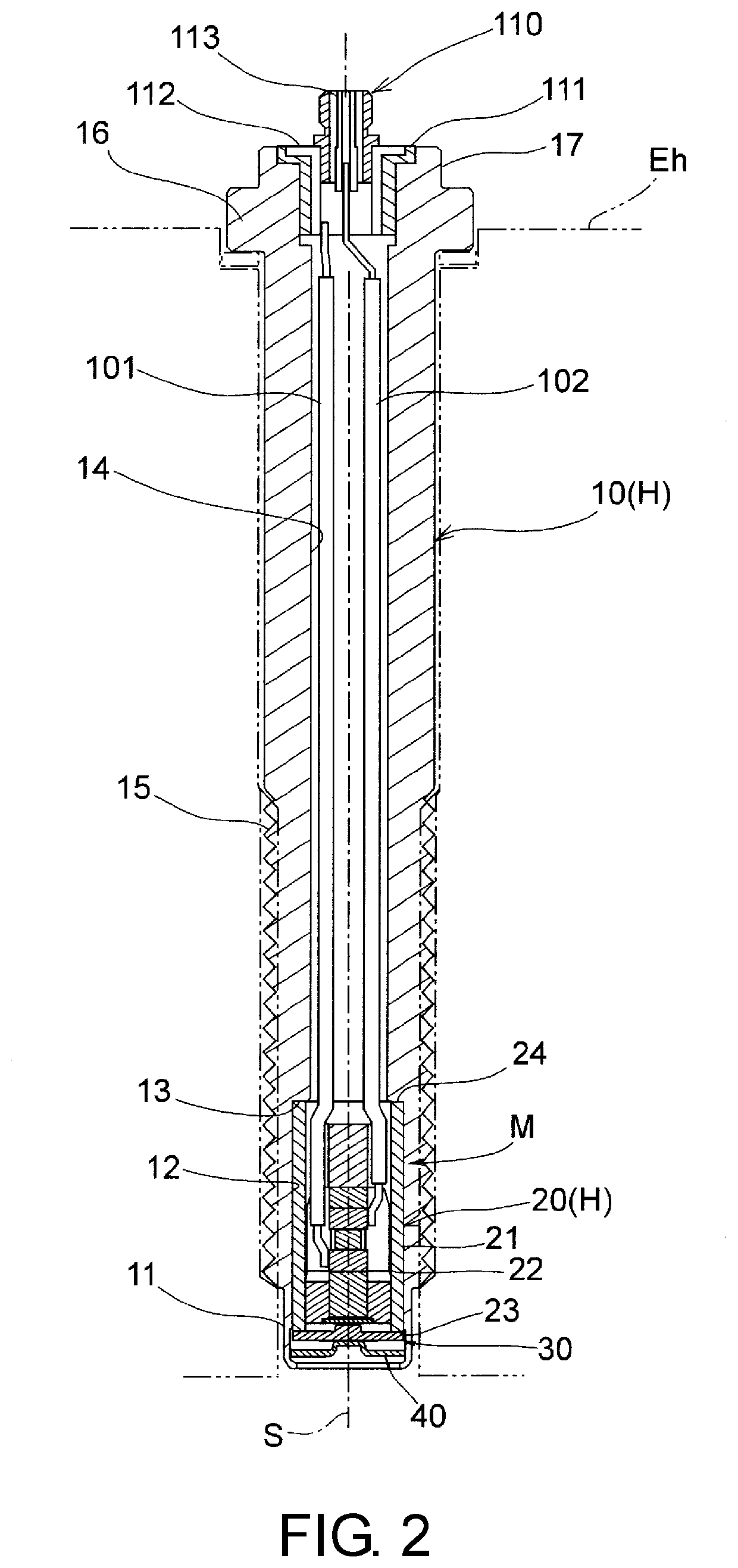
[0020]As illustrated in FIG. 2, a pressure sensor is attached to a cylinder head Eh of an engine and detects a pressure of a combustion gas as a pressure medium inside a combustion chamber.
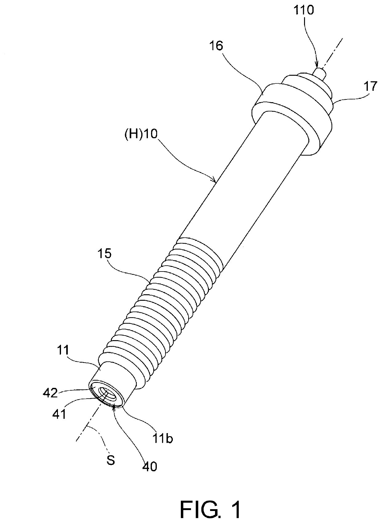
[0021]As illustrated in FIGS. 1 to 3, the pressure sensor according to the first embodiment includes an external housing 10 and a sub-housing 20 serving as a cylindrical housing H which defines an axis S, a diaphragm 30, a heat shielding plate 40, a holding plate 50, a positioning member 60, a heat insulation member 70, a pressure measurement member 80, a preload applying member 90, a lead wire 101 serving as a first conductor, a lead wire 102 serving as a second conductor, and a connector 110.
[0022]Here, the pressure measurement member 80 is constituted of a first electrode 81, a piezoelectric substance 82, and a second electrode 83 which are stacked in this order in an axis S direction from a tip side of the housing.
[0023]The preload applying member 90 is constituted of a fixing member 91 and a...
second embodiment
[0139]In the second embodiment, the tip tubular part 11 comes into line contact with the outer circumferential edge part 42b of the annular isolation part 42 to define a clearance C2 between the tip tubular part 11 and the outer circumferential surface 42a of the annular isolation part 42 in the radial direction and is bent to hold the heat shielding plate 40.
[0140]That is, a tip part 11c of the tip tubular part 11 is subjected to caulking processing in a manner of being inclined with respect to the outer circumferential surface 42a of the heat shielding plate 40, the inner circumferential wall 11a comes into contact with the outer circumferential edge part 42b of the annular isolation part 42, and the heat shielding plate 40 is held on the inner side of the tip tubular part 11.
[0141]Accordingly, the clearance C2 is defined between the inner circumferential wall 11a of the tip tubular part 11 and the outer circumferential surface 42a of the heat shielding plate 40. Therefore, when t...
third embodiment
[0144]In the pressure sensor the housing H includes the ring member 120 disposed on the tip side in the axis S direction from the heat shielding plate 40 and holds the heat shielding plate 40, in addition to the external housing 10 and the sub-housing 20.
[0145]Using the same material as that of the heat shielding plate 40, for example, a metal material such as austenitic stainless steel (SUS304), the ring member 120 is formed as a toric flat plate when viewed in the axis S direction and includes an opening part 121 and an outer circumferential surface 122, as illustrated in FIG. 10.
[0146]The outer diameter dimension of the ring member 120 is formed to have a size which comes into tight contact with and is fitted to the inner side of the tip tubular part 11 of the external housing 10, that is, an outer diameter dimension equivalent to the inner diameter dimension of the inner circumferential wall 11a. In addition, the inner diameter dimension of the opening part 121 need only be a d...
PUM
| Property | Measurement | Unit |
|---|---|---|
| thickness | aaaaa | aaaaa |
| thickness | aaaaa | aaaaa |
| diameter | aaaaa | aaaaa |
Abstract
Description
Claims
Application Information
 - R&D
- Intellectual Property
- Life Sciences
- Materials
- Tech Scout
- Unparalleled Data Quality
- Higher Quality Content
- 60% Fewer Hallucinations
Browse by: Latest US Patents, China's latest patents, Technical Efficacy Thesaurus, Application Domain, Technology Topic, Popular Technical Reports.
© 2025 PatSnap. All rights reserved.Legal|Privacy policy|Modern Slavery Act Transparency Statement|Sitemap|About US| Contact US: help@patsnap.com