Cask with ventilation control for spent nuclear fuel storage

a technology of nuclear fuel storage and cask, which is applied in the field of cask, can solve the problems of high radioactive snf in the fuel assembly still producing considerable heat which must be dissipated, stainless steel becomes vulnerable to stress corrosion cracking (scc), and on-site canister storage facilities, often called independent spent fuel storage installations (isfsis), are particularly vulnerable to scc damage, and achieves easy adjustment, increase or decrease the airflow rate, and mitigate the threat of s

Pending Publication Date: 2021-12-30
HOLTEC INT
View PDF0 Cites 2 Cited by
  • Summary
  • Abstract
  • Description
  • Claims
  • Application Information

AI Technical Summary

Benefits of technology

The invention is a ventilated cask for storing a canister that reduces the risk of SCC (semiconductor cancer) caused by the heat emitted by the canister. The cask has a natural air ventilation system that allows the user to adjust the rate of airflow as needed. This helps to maintain the canister at a safe temperature and reduces the risk of SCC. The airflow rate can be adjusted both over time and seasonally to ensure the canister remains at its maximum safe temperature.

Problems solved by technology

In addition to emitting neutron and gamma radiation) requiring protective shielding, the highly radioactive SNF in the fuel assemblies still produces considerable heat which must be dissipated to avoid damage to the fuel assemblies stored in the canister.
Classical metallurgy teaches that stainless steel becomes vulnerable to stress corrosion cracking (SCC) if the material is subject to a tensile stress field and the environment has high humidity and halide species; a condition common to many marine environments.
Thus, on-site canister storage facilities, often called Independent Spent Fuel Storage Installations (ISFSIs), located at the seacoast are especially vulnerable to SCC damage if subjected to prolonged exposure to the site's ambient environment.
Under a sufficiently prolonged service condition, there is a risk of the bottom region of the canister developing SCC over time.
The weld seams and the adjacent heat affected zones are particularly vulnerable to SCC.
Notably, the extent of the canister's lower region that is vulnerable to SCC increases as the decay heat generated by the contained fuel declines monotonically with time resulting in the canister wall concomitantly becoming gradually cooler.
Thus, threat of SCC grows over time as the canister ages.
Prior ventilated casks typically have no provisions to allow adjustment and control over the amount of ventilation air flow through the casks over time to reflect the need to keep the canister warmer at a desired temperature as its heat emission drops.

Method used


Image

  • Cask with ventilation control for spent nuclear fuel storage
  • Cask with ventilation control for spent nuclear fuel storage
  • Cask with ventilation control for spent nuclear fuel storage

Examples


first embodiment

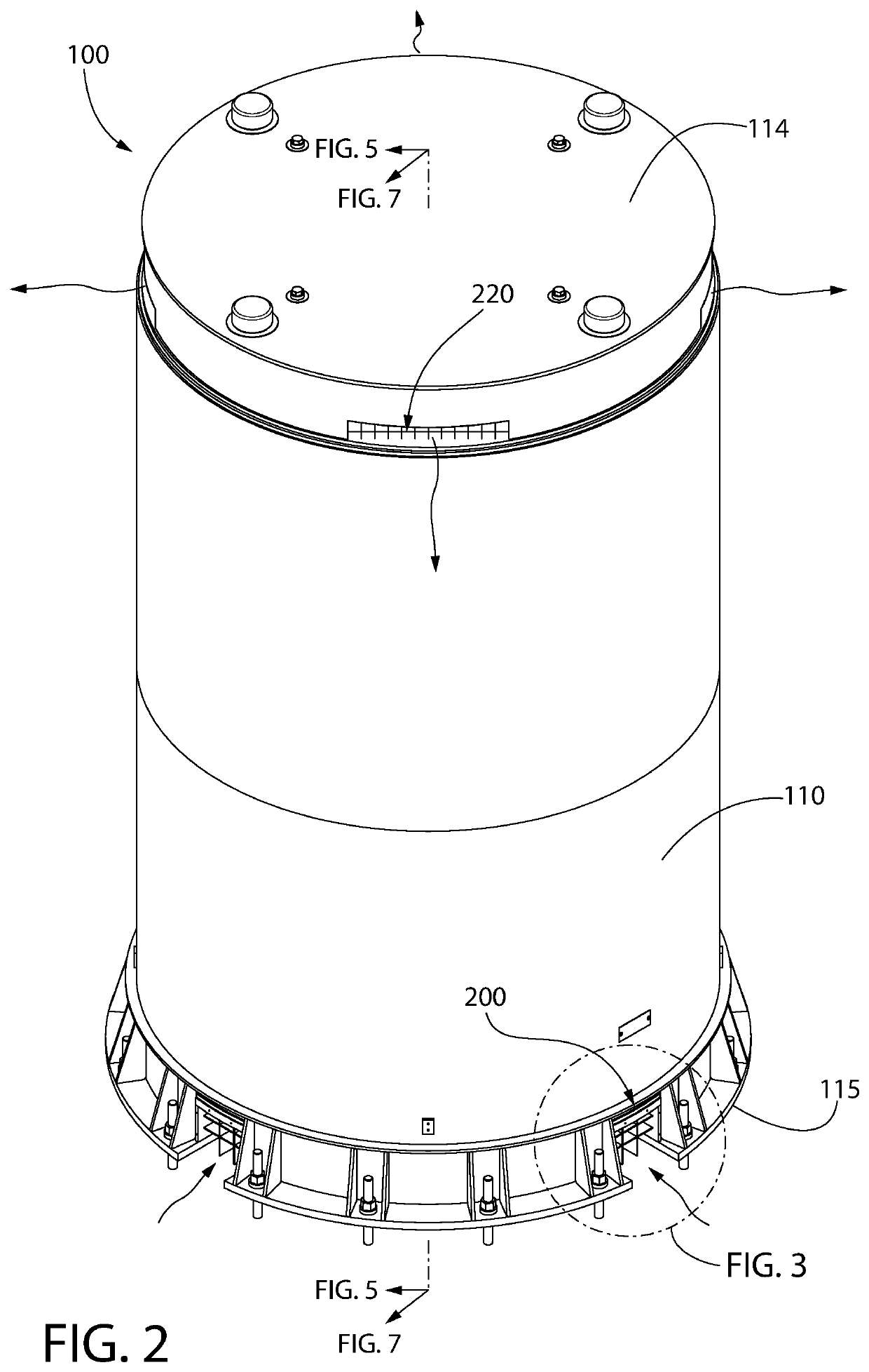
[0055]FIGS. 1-15 depict various aspects of a nuclear fuel storage system generally comprising a passively cooled and naturally ventilated outer storage module or cask 100. Cask 100 is constructed for above grade placement such as on a concrete slab. The cask has an internal cross-sectional area configured to hold only a single spent nuclear fuel (SNF) canister 101 loaded with SNF assemblies (not shown) emitting radiation and substantial amounts of decay heat.

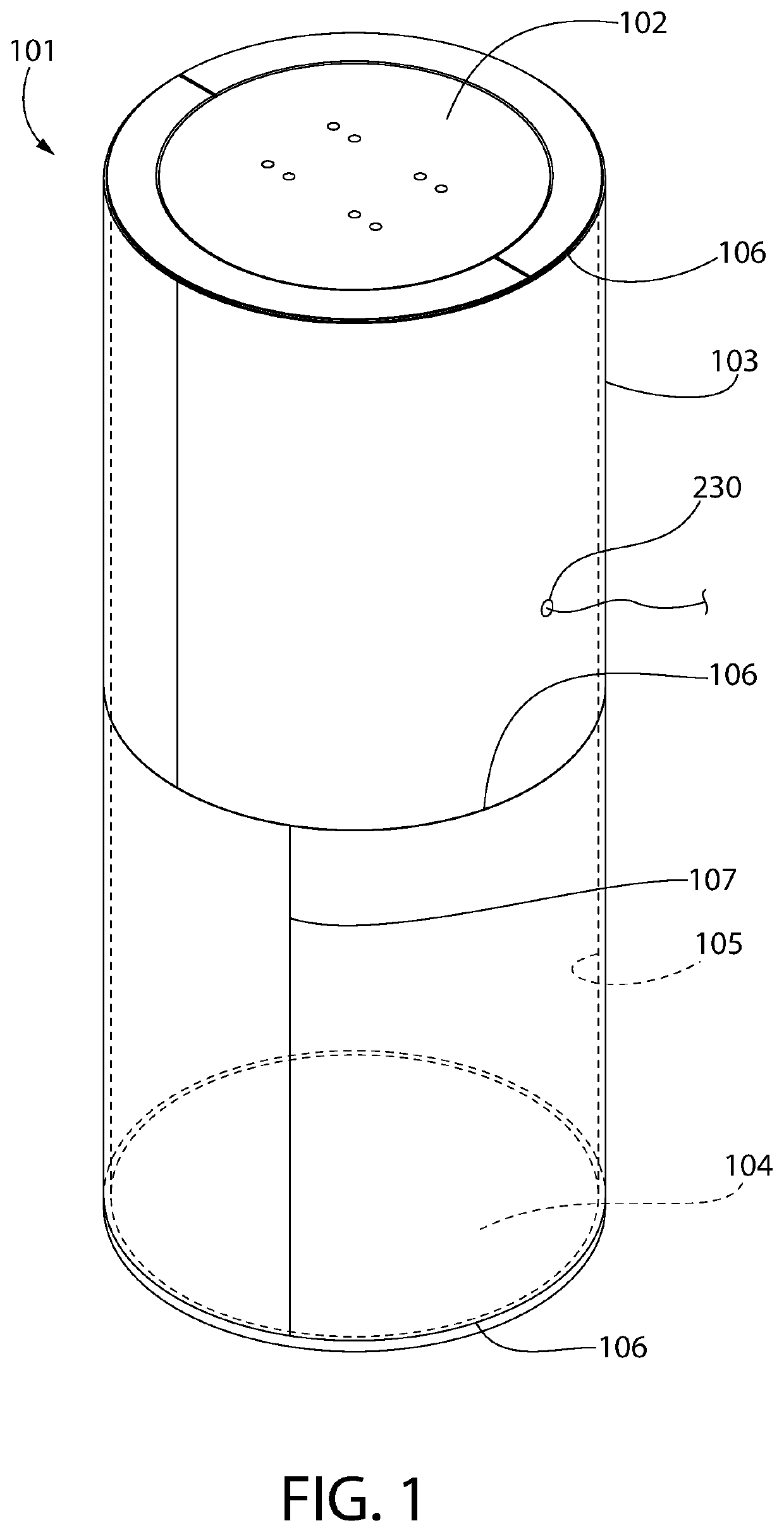
[0056]Canister 101 is a vertically elongated and hermetically sealed (i.e. gas tight) vessel in one embodiment comprising cylindrical shell 103, bottom closure plate 104 affixed to a bottom end of the shell, and a lid coupled to a top end of the shell. The lid and bottom closure plate may be hermetically seal welded to the shell via circumferentially continuous girth seal welds 106 at the weld seams. Shell 103 may be formed one or more rolled metal plate segments 103a joined by longitudinal seal welds 107 at the weld seams. A co...

second embodiment

[0093]FIGS. 16-31 depict various aspects of a nuclear fuel storage system generally comprising a passively cooled and naturally ventilated outer storage module or cask 300. Cask 300 is constructed for partial and substantial underground / below grade placement wherein a majority of the height of the cask is located below grade and the entirety of the SNF canister 101 is below grade for radiation shielding provided by the surround embedment. Whereas above grade storage cask 100 previously described herein is heavily radiation shielded, storage cask 300 conversely is unshielded. Instead, cask 300 utilizes the surrounding at grade and below grade embedment materials such as concrete and engineered fill (e.g., compacted soil, crushed stone, masonry waste material, etc. and combinations thereof) to block and absorb the radiation emitted by the SNF inside the nuclear waste fuel canister 101. Cask 300 is compatible for use in underground nuclear waste fuel and high level waste storage system...


PUM


Abstract

A natural passively cooled ventilated cask includes a cavity which holds a canister containing heat and radiation emitting spent nuclear fuel assemblies. Cooling air inlet ducts draw ambient cooling air inwards into a lower portion of the cavity. The air heated by the canister flows upwards along the canister and is discharged from at least one air outlet duct formed by the cask lid to atmosphere via natural convective thermo-siphon flow. The air inlet ducts or at least one outlet duct in one embodiment may be fitted with an adjustable shutter plate which allows the flowrate of air entering the cask to be increased or decreased to maintain a predetermined canister maximum temperature limit selected in part to prevent the onset of stress corrosion cracking of the canister welds. Other embodiments may use a fixed orifice plate replaceable over time to maintain the minimum temperature.

Description

CROSS-REFERENCE TO RELATED APPLICATIONS[0001]The present application claims the benefit of U.S. Provisional Application No. 63 / 043,812 filed Jun. 25, 2020; which is incorporated herein by reference in its entirety.BACKGROUND[0002]The present invention relates generally to ventilated overpacks or cask used for dry storage and / or transport of high level nuclear waste from nuclear power generating plants or other nuclear facilities, and more particularly to such a cask with controllable ventilation air flow.[0003]In the operation of nuclear reactors, the nuclear energy source is typically in the form of a plurality of hollow Zircaloy tubes each filled with enriched uranium pellets, which are collectively arranged in assemblages referred to as fuel assemblies. When the energy in the fuel assembly has been depleted to a certain predetermined level, the fuel assembly is removed from the nuclear reactor and referred to as used or spent nuclear fuel (“SNF”). The standard structure used to p...

Claims


Application Information

Patent Timeline
IPC IPC(8): G21F5/005G21F5/10G21F9/34
CPCG21F5/005G21F9/34G21F5/10
Inventor SINGH, KRISHNA P.BIDRAWN, FREDERICK R.
Owner HOLTEC INT
Why Eureka
Try Eureka