Ring-shaped cofferdam and temporary pit excavation structure using tapered square pipe, and construction method thereof

a technology of tapered square pipes and ring-shaped cofferdams, which is applied in excavations, foundation engineering, construction, etc., can solve the problems of insufficient strength of the related art, difficulty in ensuring a sufficient work space, and difficulty in construction, so as to achieve convenient construction, secure a work space, and simple structure

Active Publication Date: 2021-11-11
KANG BYUNG KWAN
View PDF0 Cites 1 Cited by
  • Summary
  • Abstract
  • Description
  • Claims
  • Application Information

AI Technical Summary

Benefits of technology

[0031]The ring-shaped cofferdam and temporary pit excavation structure using tapered square pipes according to an embodiment of the present invention uses tapered square pipes having a trapezoidal cross-section and uses an arch structure such that a component of force (compression force) acts between the tapered square pipes, so there is little influence by excavation depth, and accordingly, the structure can be applied to a site with large depth.
[0032]Further, the ring-shaped cofferdam and temporary pit excavation structure using tapered square pipes according to an embodiment of the present invention does not need a wale, a strut, and a center pile, so it is advantageous to secure a work space.
[0033]Further, the ring-shaped cofferdam and temporary pit excavation structure using tapered square pipes according to an embodiment of the present invention has a simple structure, so the structure that can be easily constructed and can be clearly structurally analyzed.
[0035]Further, the ring-shaped cofferdam and temporary pit excavation structure using tapered square pipes according to an embodiment of the present invention makes it possible to reduce a construction period and can be easily disassembled because welding or filling with concrete is not used.
[0036]As described above, the present invention enables construction with very less components in comparison to the related art (there is no need for a wale, a strut, a center pile, etc.), so it is economically excellent.

Problems solved by technology

However, this temporary structure of the related art is insufficient in strength because the sheet piles 1 are used, so the members such as the wales 2, struts 3, and center piles 4 are additionally required.
Further, due to the additionally installed wales 2, struts 3, and center piles 4, the temporary structure of the related art has the problem that it is difficult to secure a sufficient work space, construction is difficult, and a large cost is required because it is difficult to reduce the construction period.
Further, there is Korean Patent No. 10-1022841 (titled, WAVE PATTERN STEEL BEAM OR CUTTING PATTERN STEEL BEAM HAVING A TEMPORARY COFFER DAM) in relation to a cofferdam in the related art, but, which has a problem that the strength of a single sheet pile wall installed in a row is low due to the characteristics of steel, to the wall is easily deformed by side pressure and there is a need for a specific method for supporting the wall using supports, etc.
However, since cofferdam walls are usually installed in the water or ground with regular intervals, there is a need for underwater work by divers when they are installed in the water, and it is difficult to realistically install any supporting structure for the sections of walls embedded in the ground.
Accordingly, such a method using tie cables in the related art has many problems.
However, this technology still has a problem of inconvenience in construction that it is required to fill spaces with a filler because sheet piles are used.
Further, the strength is not sufficient for areas with large side pressure.

Method used


Image

  • Ring-shaped cofferdam and temporary pit excavation structure using tapered square pipe, and construction method thereof
  • Ring-shaped cofferdam and temporary pit excavation structure using tapered square pipe, and construction method thereof
  • Ring-shaped cofferdam and temporary pit excavation structure using tapered square pipe, and construction method thereof

Examples


Embodiment Construction

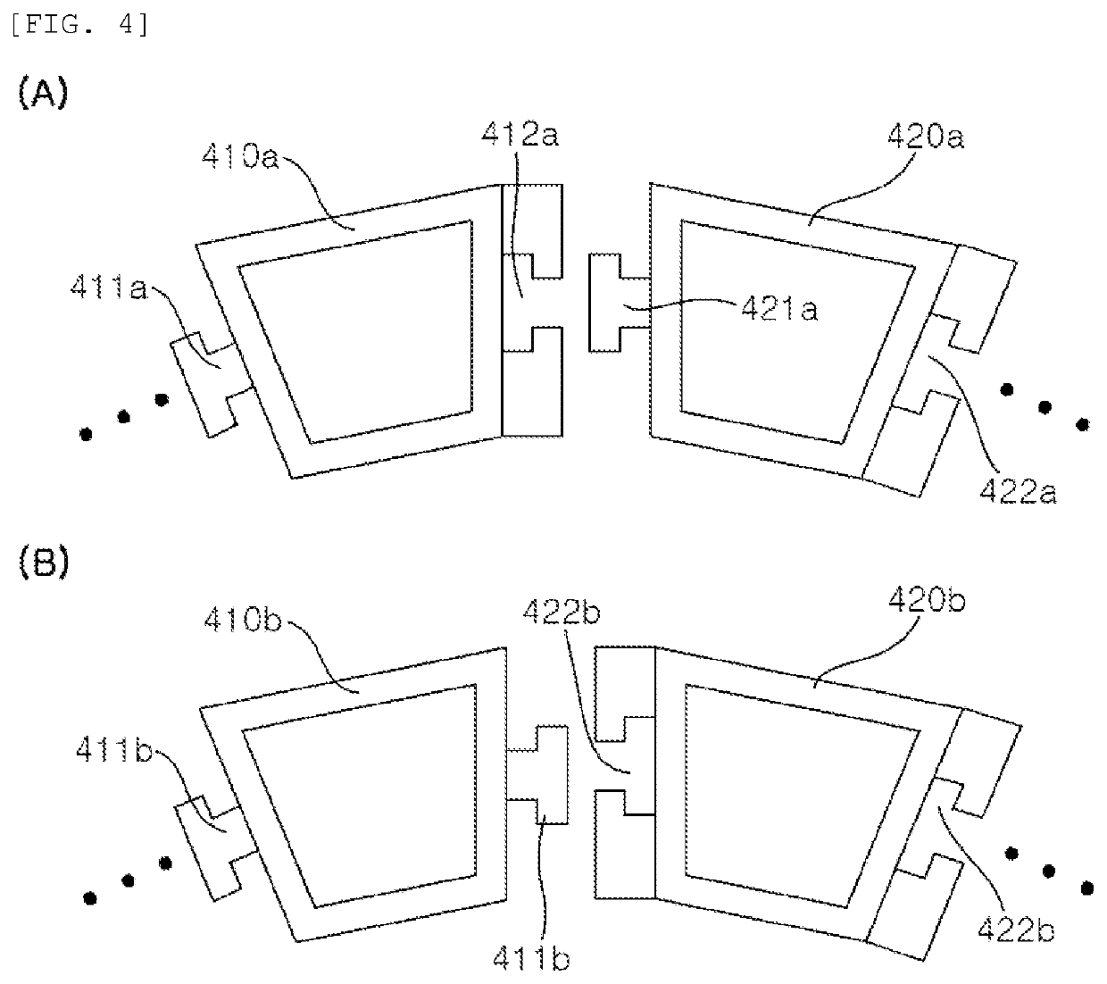
[0068]FIGS. 4 to 6 are views showing another coupling structure of a ring-shaped cofferdam and temporary pit excavation structure using tapered square pipes according to an embodiment of the present invention.

[0069]Referring to FIG. 4A, in a ring-shaped cofferdam and temporary pit excavation structure using tapered square pipes according to an embodiment of the present invention, when a first tapered square pipe 410a that is one of a plurality of tapered square pipes 410a and 420a has a coupling protrusion 411a formed in the longitudinal direction and a second tapered square pipe 420a that is one of the plurality of tapered square pipes 410a and 420a has a coupling groove 422a formed in the longitudinal direction to fit the coupling protrusion 411a therein, the coupling protrusion 411a of the first tapered square pipe 410a may have a T-shaped cross-section and the coupling groove 422a of the second tapered square pipe 420a may be formed to correspond go the coupling protrusion 411a....


PUM


Abstract

A ring-shaped cofferdam and temporary pit excavation structure using tapered square pipes includes a plurality of tapered square pipes a trapezoidal cross-section, in which the plurality of tapered square pipes each have a coupling protrusion or a coupling groove formed in a longitudinal direction on a first side, the plurality of tapered square pipes each have a coupling protrusion or a coupling groove formed in the longitudinal direction on a second side, the plurality of tapered square pipes are assembled by coupling the coupling protrusions and the coupling grooves, a long side of two parallel sides of the trapezoid is disposed outside, and a short side is disposed inside.

Description

TECHNICAL FIELD[0001]The present invention relates to a ring-shaped cofferdam and temporary pit excavation structure using tapered square pipes and, more particularly, to a ring-shaped cofferdam and temporary pit excavation structure using tapered square pipes having a trapezoidal cross-section.BACKGROUND ART[0002]A cofferdam, which is a structure temporarily installed to block water or earth and sand at construction sites, is generally constructed by boring or driving usually H-beams, cylindrical pies, or sheet piles.[0003]FIG. 1 is a view showing the configuration of a temporary structure for blocking earth and sand in the related art. Referring to FIG. 2, the structure includes sheet piles 1 disposed outside, wales 2 horizontally attached to the sheet piles 2, struts 3 perpendicularly connected to the wales 2 in the same plane, and center piles 4 vertically installed in the ground.[0004]However, this temporary structure of the related art is insufficient in strength because the s...

Claims


Application Information

Patent Timeline
Patent Type & Authority Applications(United States)
IPC IPC(8): E02D19/04
CPCE02D19/04E02D2600/10E02D2600/20E02D2200/1657E02D17/04E02D13/04E02D17/08E02D17/02E02D17/06E02D19/02E02D19/06E02D2200/16
Inventor KANG, BYUNG KWAN
Owner KANG BYUNG KWAN
Why Eureka
Try Eureka